[System Maintenance Notice]
Due to ongoing system maintenance, the site search and specification search functions are temporarily unavailable. We apologize for any inconvenience this may cause and appreciate your understanding.
【Notification of Manufacturer Change for Panasonic Industrial Devices SUNX Products and Panasonic Industrial Devices SUNX Tatsuno Products】
From April 1, 2024, the terms "Panasonic Industrial Devices SUNX Co., Ltd." and "Panasonic Industrial Devices SUNX Tatsuno Co., Ltd."
in this page and in the manuals and other documents to be downloaded will all be replaced with "Panasonic Industry Co., Ltd." and applied accordingly.
Ultra-compact Photoelectric Sensor EX-20 Ver.2
Sensing characteristics
EX-21□ EX-23□ EX-29□ EX-22□
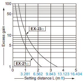
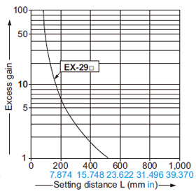
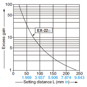
Correlation between setting distance and excess gain
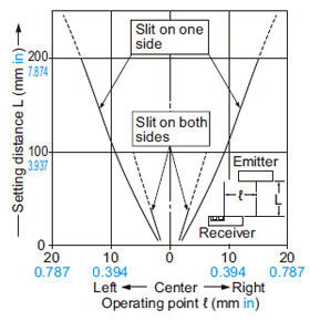
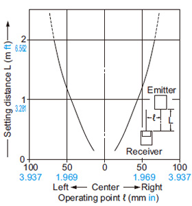
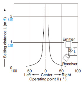
EX-21□
Thru-beam type
Parallel deviation |
|---|
 |
|
|
Angular deviation |
|---|
 |
|
|
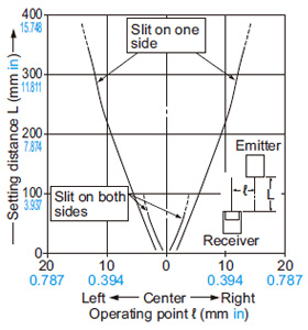
Parallel deviation with round slit masks
(ø0.5 mm ø0.020 in) |
|---|
 |
|
|
Parallel deviation with rectangular slit masks
(0.5 × 3 mm 0.020 × 0.118 in) |
|---|
 |
|
|
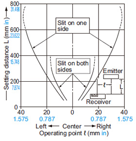
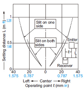
EX-23□
Thru-beam type
Parallel deviation |
|---|
 |
|
|
Angular deviation |
|---|
 |
|
|
Parallel deviation with round slit masks
(ø0.5 mm ø0.020 in) |
|---|
 |
|
|
Parallel deviation with rectangular slit masks
(0.5 × 3 mm 0.020 × 0.118 in) |
|---|
 |
| Parallel deviation with rectangular slit |
|
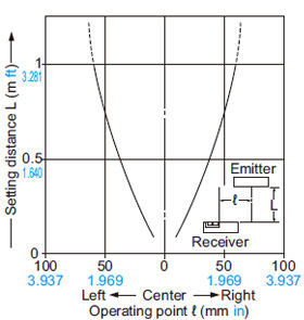
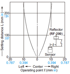
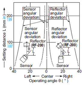
EX-29□
Retroreflective type
Parallel deviation |
|---|
 |
|
|
Angular deviation |
|---|
 |
|
|
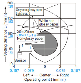
EX-22□
Diffuse reflective type
Sensing field |
|---|
 |
|
|
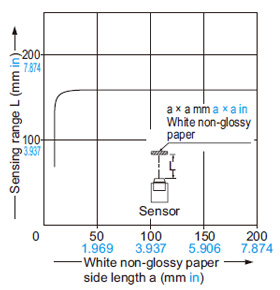
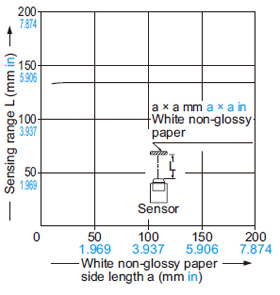
Correlation between sensing object size and sensing range
|
|
As the sensing object size becomes smaller than the standard size (white non-glossy paper 200 × 200 mm 7.874 × 7.874 in), the sensing range shortens, as shown in the left graph. |
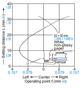
EX-24□
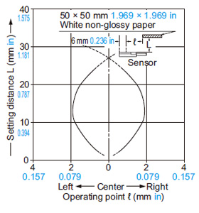
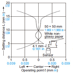
Convergent reflective type
Sensing fields
• Horizontal (left and right) direction |
|---|
 |
|
|
• Vertical (up and down) direction |
|---|
 |
|
|
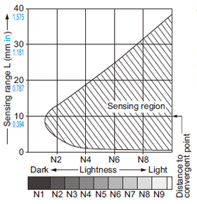
Correlation between lightness and sensing range
|
|
The sensing region (typical) is represented by oblique lines in the left figure. However, the sensitivity should be set with enough margin because of slight variation in products.
(Lightness shown on the left may differ slightly from the actual object condition.) |
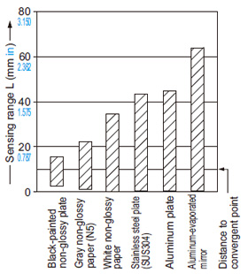
Correlation between material (50 × 50 mm 1.969 × 1.969 in) and sensing range
|
|
The bars in the graph indicate the sensing range (typical) for the respective material.
However, there is a slight variation in the sensing range depending on the product.
Further, if there is a reflective object (conveyor, etc.) in the background of the sensing object, since it affects the sensing, separate it by more than twice the sensing range shown in the left graph. |
EX-26□
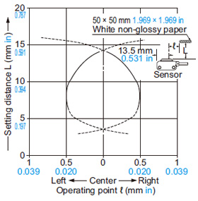
Convergent reflective type
Sensing fields
• Horizontal (left and right) direction |
|---|
 |
|
|
• Vertical (up and down) direction |
|---|
 |
|
|
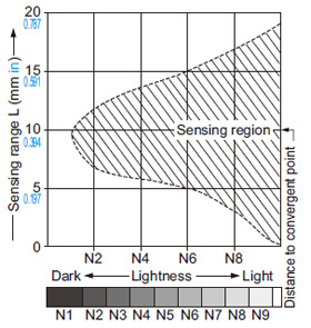
Correlation between lightness and sensing range
|
|
The sensing region (typical) is represented by oblique lines in the left figure. However, the sensitivity should be set with enough margin because of slight variation in products.
(The graph is drawn for the maximum sensitivity setting.)
(Lightness shown on the left may differ slightly from the actual object condition.) |
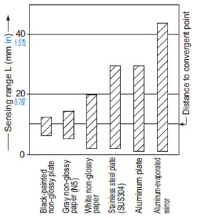
Correlation between material (50 × 50 mm 1.969 × 1.969 in) and sensing range
|
|
The bars in the graph indicate the sensing range (typical) for the respective material. However, there is a slight variation in the sensing range depending on the productFurther, if there is a reflective object (conveyor, etc.) in the background of the sensing object, since it affects the sensing, separate it by more than twice the sensing range shown in the left graph, or adjust the sensitivity adjuster.
(The graph is drawn for the maximum sensitivity setting.) |
EX-28□
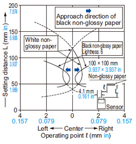
Narrow-view reflective type
Sensing field |
|---|
 |
|
|
Correlation between sensing object size and sensing range
|
|
As the sensing object size becomes smaller than the standard size (white non-glossy paper 100 × 100 mm 3.937 × 3.937 in), the sensing range shortens, as shown in the left graph. |
Return to top
Return to top

 Business
> Industrial Devices
> Automation Controls Top
> FA Sensors & Components
> Sensors
> Photoelectric Sensors / Laser Sensors
> Ultra-compact Photoelectric Sensor EX-20 Ver.2
> Sensing characteristics
Business
> Industrial Devices
> Automation Controls Top
> FA Sensors & Components
> Sensors
> Photoelectric Sensors / Laser Sensors
> Ultra-compact Photoelectric Sensor EX-20 Ver.2
> Sensing characteristics