[System Maintenance Notice]
Due to ongoing system maintenance, the site search and specification search functions are temporarily unavailable. We apologize for any inconvenience this may cause and appreciate your understanding.
【Notification of Manufacturer Change for Panasonic Industrial Devices SUNX Products and Panasonic Industrial Devices SUNX Tatsuno Products】
From April 1, 2024, the terms "Panasonic Industrial Devices SUNX Co., Ltd." and "Panasonic Industrial Devices SUNX Tatsuno Co., Ltd."
in this page and in the manuals and other documents to be downloaded will all be replaced with "Panasonic Industry Co., Ltd." and applied accordingly.

 Business
> Industrial Devices
> Automation Controls Top
> FA Sensors & Components
> Sensors
> Inductive Proximity Sensors
> Cylindrical Inductive Proximity Sensor [Amplifier Built-in / DC 3-wire Type] GX-300
> Cautions For Use
Business
> Industrial Devices
> Automation Controls Top
> FA Sensors & Components
> Sensors
> Inductive Proximity Sensors
> Cylindrical Inductive Proximity Sensor [Amplifier Built-in / DC 3-wire Type] GX-300
> Cautions For Use
Cylindrical Inductive Proximity Sensor [Amplifier Built-in / DC 3-wire Type] GX-300
|
Cautions For Use
| ・ | This Web site is a guide to select a suitable product. Be sure to read instruction manual attached to the product prior to its use. |
|---|
- Never use this product as a sensing device for personnel protection.
- In case of using sensing devices for personnel protection, use products which meet laws and standards, such as OSHA, ANSI or IEC etc., for personnel protection applicable in each region or country.
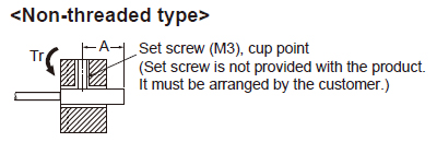
Mounting
- The tightening torque should be under the value given below.
|
|
|||||||||||||||||||||||||||||||||||||||||||||||||||||
|
|
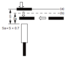
Installing small-diameter sensor
- Please use the sensor after confirming the installation distance by following (a) and (b) with an actual detection object when you install.
| (a) | The detection distance receives the influence by the material of the detection object, thickness, shape, and the size. So, the detection object is brought close to the front side of the sensor and detection distance (S) is measured. For the effect of the material, see the graph, "Correlation between sensing object size and sensing range". |
|---|---|
| (b) | Please decide installation distance (Sa) with S × 70% or less after measuring sensing distance(S). |
- Please install the sensor to come within the range of (Sa) when the detection object moves from vertical direction.
- Please install the sensor to pass within the range of (Sa) when the detection object moves from horizontal direction.
- When using the sensor, refer to the "Standard sensing object" specified in the specifications and the graph, "Correlation between sensing object size and sensing range".
|
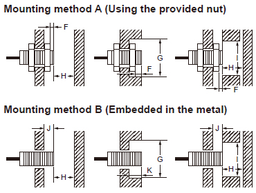
Distance from surrounding metal
- As metal around the sensor may affect the sensing performance, pay attention to the following points.
Influence of surrounding metal
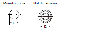
- The surrounding metal will affect the sensing performance. Keep the minimum distance specified in the table below.
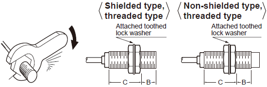
- When mounting the sensor using a nut, use the nut and washer provided with the product.
- The type of the provided nut varies in different models. See the external dimensions diagrams for the detail of the shape.
|
(Unit:mm in)
| Model No. (Shielded type) |
Mounting method A | Mounting method B | |||||||
|---|---|---|---|---|---|---|---|---|---|
| F | G | H | I | J | G | K | H | I | |
| GX-303S | - | - | - | - | 0 | ø3 ø0.118 |
0 | 3 0.118 |
8 0.315 |
| GX-304S | - | - | - | - | 0 | ø4 ø0.157 |
0 | 5 0.197 |
10 0.394 |
| GX-305S | - | - | - | - | 0 | ø5.4 ø0.213 |
0 | 3 0.118 |
8 0.315 |
| GX-305M | 0 | ø5 ø0.197 |
5 0.197 |
10 0.394 |
0 | ø5 ø0.197 |
0 | 5 0.197 |
10 0.394 |
| GX-308M | 0 | ø8 ø0.315 |
4.5 0.177 |
12 0.472 |
0 | ø8 ø0.315 |
0 | 4.5 0.177 |
12 0.472 |
| GX-312M | 0 | ø12 ø0.472 |
8 0.315 |
18 0.709 |
0 | ø12 ø0.472 |
0 | 8 0.315 |
18 0.709 |
| GX-318M | 0 | ø18 ø0.709 |
20 0.787 |
27 1.063 |
0 | ø18 ø0.709 |
0 | 20 0.787 |
27 1.063 |
| GX-330M | 0 | ø30 ø1.181 |
40 1.575 |
45 1.772 |
0 | ø30 ø1.181 |
0 | 40 1.575 |
45 1.772 |
| GX-308MK | 0 | ø8 ø0.315 |
4.5 0.177 |
12 0.472 |
0 | ø8 ø0.315 |
0 | 4.5 0.177 |
12 0.472 |
| GX-312MK | 0 | ø18 ø0.709 |
12 0.472 |
18 0.709 |
2.4 0.094 |
ø18 ø0.709 |
2.4 0.094 |
12 0.472 |
18 0.709 |
| GX-318MK | 0 | ø27 ø1.063 |
24 0.945 |
27 1.063 |
3.6 0.142 |
ø27 ø1.063 |
3.6 0.142 |
24 0.945 |
27 1.063 |
| GX-330MK | 0 | ø45 ø1.772 |
45 1.772 |
45 1.772 |
6 0.236 |
ø45 ø1.772 |
6 0.236 |
45 1.772 |
45 1.772 |
| Model No. (Non-shielded type) |
Mounting method A | Mounting method B | |||||||
|---|---|---|---|---|---|---|---|---|---|
| F | G | H | I | J | G | K | H | I | |
| GX-308ML | 6 0.236 |
ø24 ø0.945 |
8 0.315 |
24 0.945 |
6 0.236 |
ø24 ø0.945 |
6 0.236 |
8 0.315 |
24 0.945 |
| GX-312ML | 11 0.433 |
ø40 ø1.575 |
20 0.787 |
36 1.417 |
15 0.591 |
ø40 ø1.575 |
15 0.591 |
20 0.787 |
36 1.417 |
| GX-318ML | 18 0.709 |
ø55 ø2.165 |
40 1.575 |
54 2.126 |
22 0.866 |
ø55 ø2.165 |
22 0.866 |
40 1.575 |
54 2.126 |
| GX-330ML | 25 0.984 |
ø90 ø3.543 |
70 2.756 |
90 3.543 |
30 1.181 |
ø90 ø3.543 |
30 1.181 |
70 2.756 |
90 3.543 |
| GX-308MLK | 9 0.354 |
ø24 ø0.945 |
8 0.315 |
24 0.945 |
12 0.472 |
ø24 ø0.945 |
12 0.472 |
8 0.315 |
24 0.945 |
| GX-312MLK | 11 0.433 |
ø40 ø1.575 |
20 0.787 |
40 1.575 |
15 0.591 |
ø40 ø1.575 |
15 0.591 |
20 0.787 |
40 1.575 |
| GX-318MLK | 21 0.827 |
ø70 ø2.756 |
48 1.890 |
70 2.756 |
25 0.984 |
ø70 ø2.756 |
25 0.984 |
48 1.890 |
70 2.756 |
| GX-330MLK | 40 1.575 |
ø120 ø4.724 |
90 3.543 |
120 4.724 |
45 1.772 |
ø120 ø4.724 |
45 1.772 |
90 3.543 |
120 4.724 |
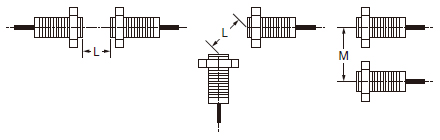
Mutual interference
- When two or more sensors are installed in parallel or face to face, keep the minimum separation distance specified below to avoid mutual interference.
|
|
|
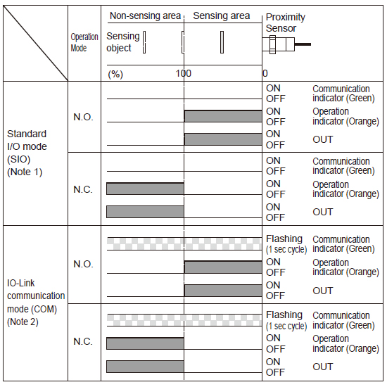
Timing chart
|
Others
- This product has been developed / produced for industrial use only.
- Do not install the product in the following locations. Doing so may result in product failure or malfunction.
∙ Outdoor locations directly subject to sunlight, rain, snow, water droplets, or oil.
∙ Locations subject to atmospheres with chemical vapors, in particular solvents and acids.
∙ Locations subject to corrosive gases. - The product may malfunction if used near ultrasonic cleaning equipment, high-frequency equipment, transceivers, cellular phones, inverters, or other devices that generate a high-frequency electric field.
- Laying the product wiring in the same conduit or duct as high-voltage wires or power lines may result in incorrect operation and damage due to induction. Wire the product using a separate conduit or independent conduit.
- The following conditions shall be observed if you use the product under an environment using cutting oil that may affect product’s life and/or performance.
∙ Usage in oil or water is prohibited. - Impact on the product life may differ depending on the oil you use. Before using the cutting oil, make sure that it should not cause deterioration or degradation of sealing components.
- Never use thinner or other solvents. Otherwise, the product surface may be dissolved.
- When turning ON the power by influence of temperature environment, an output mis-pulse sometimes occurs.
After the product has passed for 300 ms after turning ON, please use in the stable state. If the sensing object is located near the sensor’s sensing surface, an output mis-pulse may be generated for 300 ms or longer at the time of power-on.
Be sure to check the product for proper operation under actual operating condition before using. - The product is adjusted with a high degree of accuracy, so do not use in the environment with sudden temperature change.
- Do not attempt to disassemble, repair, or modify the product.
- Do not use a voltage that exceeds the rated operating voltage range. Applying a voltage that is higher than the operating voltage range may result in damage or burnout.
- Be sure that the power supply polarity and other wiring is correct. Incorrect wiring may cause explosion or burnout.
- If the power supply is connected directly without a load, the internal elements may explode or burn. Be sure to insert a load when connecting the power supply.
- Please use gloves to protect yourself from injury caused by screw.
- For the connector type and pigtailed type, check the specifications of the connector cable to be used. Please do not use it under conditions that exceed the range of its specifications of both the product and the connector cable.
- Please make sure there is no foreign matter in connector part before connecting the connector cable to the connector type and pigtailed type.
- In the IO-Link mode, the cable between the IO-Link master and sensor must have a length of 20 m 65.617 ft or less.
BY EMAIL


Requests to customers (Automation Control Components & Industrial Device) [Excluding specific product]
Requests to customers (Automation Control Components & Industrial Device) [For specific product]
Requests to customers (FA Sensors & Components [Excluding motors])
Requests to customers (Dedicated to industrial motors)
- COMPONENTS & DEVICES
- FA SENSORS & COMPONENTS
- Fiber Sensors
- Photoelectric Sensors / Laser Sensors
- Micro Photoelectric Sensors
- Light Curtains / Safety Components
- Area Sensors
- Inductive Proximity Sensors
- Particular Use Sensors
- Sensor Options
- Wire-Saving Systems
- Programmable Controllers / Interface Terminal
- Human Machine Interface
- Pressure Sensors / Flow Sensors
- Measurement Sensors
- Static Control Devices
- Laser Markers / 2D Code Readers
- Machine Vision System
- Energy Management Solutions
- Timers / Counters / FA Components
- MOTORS
![]()