[System Maintenance Notice]
Due to ongoing system maintenance, the site search and specification search functions are temporarily unavailable. We apologize for any inconvenience this may cause and appreciate your understanding.
【Notification of Manufacturer Change for Panasonic Industrial Devices SUNX Products and Panasonic Industrial Devices SUNX Tatsuno Products】
From April 1, 2024, the terms "Panasonic Industrial Devices SUNX Co., Ltd." and "Panasonic Industrial Devices SUNX Tatsuno Co., Ltd."
in this page and in the manuals and other documents to be downloaded will all be replaced with "Panasonic Industry Co., Ltd." and applied accordingly.

 Business
> Industrial Devices
> Automation Controls Top
> FA Sensors & Components
> Sensors
> Inductive Proximity Sensors
> Cylindrical Inductive Proximity Sensor [Amplifier Built-in / DC 3-wire Type] GX-300
> I/O Circuit and Wiring diagrams
Business
> Industrial Devices
> Automation Controls Top
> FA Sensors & Components
> Sensors
> Inductive Proximity Sensors
> Cylindrical Inductive Proximity Sensor [Amplifier Built-in / DC 3-wire Type] GX-300
> I/O Circuit and Wiring diagrams
Cylindrical Inductive Proximity Sensor [Amplifier Built-in / DC 3-wire Type] GX-300
|
I/O Circuit and Wiring diagrams
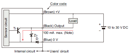
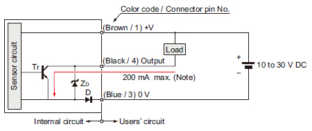
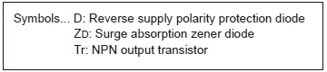
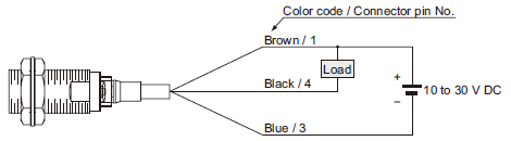
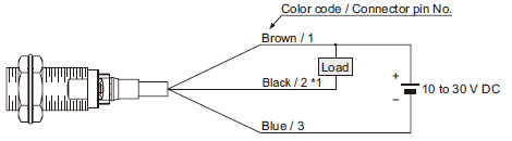
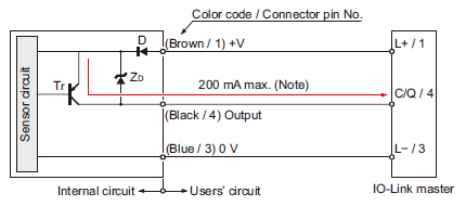
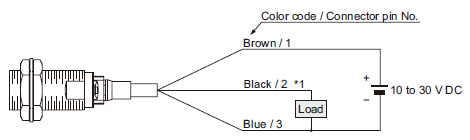
GX-3□S-□-N
GX-305M-□-N
NPN output type
|
|
|
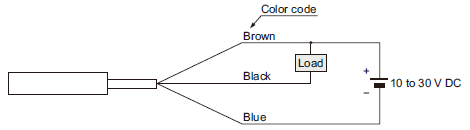
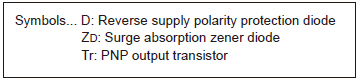
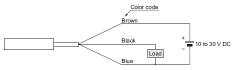
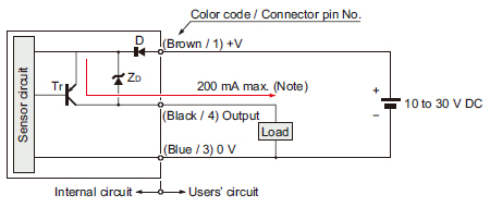
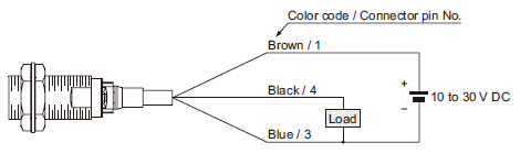
GX-3□S-□-P
GX-305M-□-P
PNP output type
|
|
|
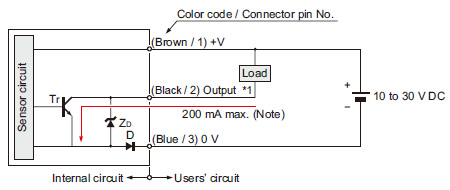
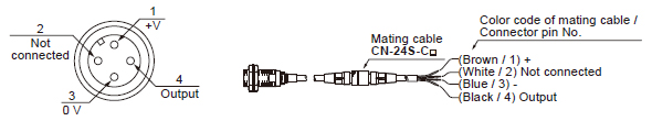
GX-3□M(K)-A-N
GX-3□ML(K)-A-N
* Excluding M5 threaded type
NPN output, Normally open type
|
|
|
|
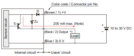
GX-3□M(K)-B-N
GX-3□ML(K)-B-N
* Excluding M5 threaded type
NPN output, Normally closed type
|
|
|
|
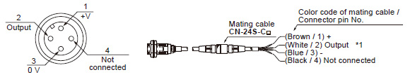
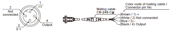
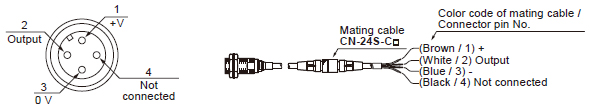
*1: Note that the lead color of the sensor and that of the matting cable are different.
GX-3□M(K)-A-P
GX-3□ML(K)-A-P
* Excluding M5 threaded type
PNP output, Normally open type
|
|
|
|

|
|
GX-3□M(K)-B-P
GX-3□ML(K)-B-P
* Excluding M5 threaded type
PNP output, Normally closed type
|
|

|
|
*1: Note that the lead color of the sensor and that of the matting cable are different.
BY EMAIL


Requests to customers (Automation Control Components & Industrial Device) [Excluding specific product]
Requests to customers (Automation Control Components & Industrial Device) [For specific product]
Requests to customers (FA Sensors & Components [Excluding motors])
Requests to customers (Dedicated to industrial motors)
- COMPONENTS & DEVICES
- FA SENSORS & COMPONENTS
- Fiber Sensors
- Photoelectric Sensors / Laser Sensors
- Micro Photoelectric Sensors
- Light Curtains / Safety Components
- Area Sensors
- Inductive Proximity Sensors
- Particular Use Sensors
- Sensor Options
- Wire-Saving Systems
- Programmable Controllers / Interface Terminal
- Human Machine Interface
- Pressure Sensors / Flow Sensors
- Measurement Sensors
- Static Control Devices
- Laser Markers / 2D Code Readers
- Machine Vision System
- Energy Management Solutions
- Timers / Counters / FA Components
- MOTORS
![]()