Safety Light Curtain Type 2 SF2B Ver.2 (Discontinued Products)
We are sorry, the products have been discontinued. Please refer to the details of the discontinued products and the recommended substitutes list below.
|
|
I/O Circuit and Wiring diagrams
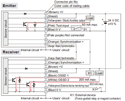
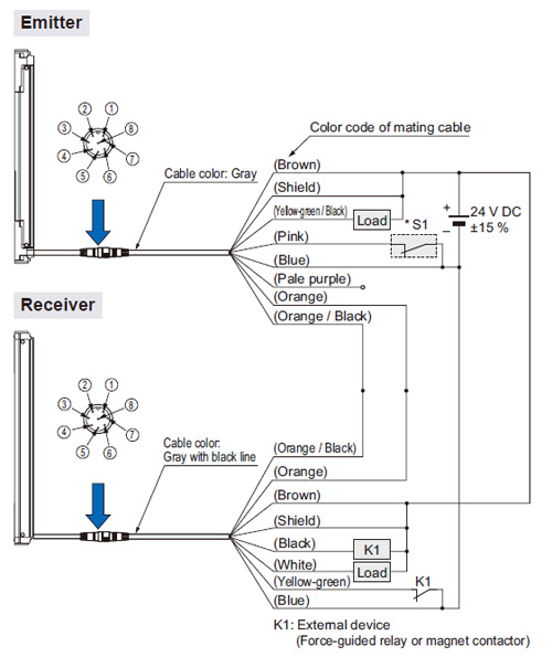
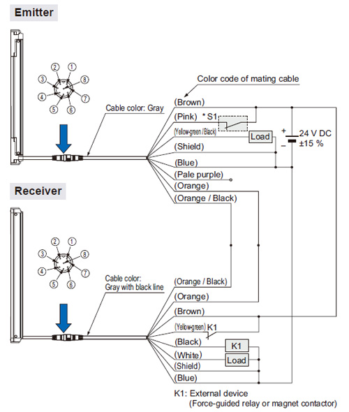
NPN output type
| When using a SF2B-CCB□ or SF2B-CB□ bottom cap cable |
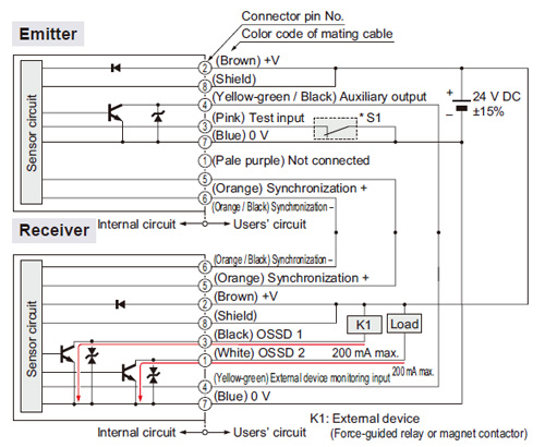
I/O circuit diagram
<In case of setting the external device monitoring function to enabled> |
 |
|
| Note: |
Unused wires must be insulated to ensure that they do not come into contact with wires already in use. |
CAUTION
Construct the interlock (reset input) circuit separately. |
*S1
| Switch S1 |
| ・ |
Test input
Open: Emission halt
0 to +1.5 V (source current 5 mA or less): Emission |
Wiring diagram
<In case of setting the external device monitoring function to enabled> |
 |
|
| Note: |
Unused wires must be insulated to ensure that they do not come into contact with wires already in use. |
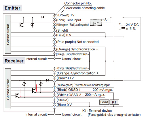
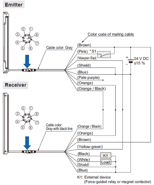
I/O circuit diagram
<In case of setting the external device monitoring function to disabled>
- In order to disable the external device monitoring function, connect the auxiliary output and external device monitoring input. At such times, do not connect a load to the auxiliary output.
| Note: |
Unused wires must be insulated to ensure that they do not come into contact with wires already in use. |
CAUTION
Construct the interlock (reset input) circuit separately. |
*S1
| Switch S1 |
| ・ |
Test input
Open: Emission halt
0 to +1.5 V (source current 5 mA or less): Emission |
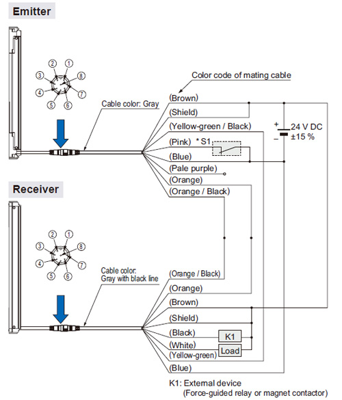
Wiring diagram
<In case of setting the external device monitoring function to disabled> |
 |
|
| Note: |
Unused wires must be insulated to ensure that they do not come into contact with wires already in use. |
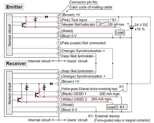
PNP output type
| When using a SF2B-CCB□ or SF2B-CB□ bottom cap cable |
I/O circuit diagram
<In case of setting the external device monitoring function to enabled> |
 |
|
| Note: |
Unused wires must be insulated to ensure that they do not come into contact with wires already in use. |
CAUTION
Construct the interlock (reset input) circuit separately. |
*S1
| Switch S1 |
| ・ |
Test input
Open: Emission halt
Vs to Vs – 2.5 V (sink current 5 mA or less): Emission (Note 2) |
Notes:
| 1) |
Unused wires must be insulated to ensure that they do not come into contact with wires already in use. |
| 2) |
Vs is the applying supply voltage. |
Wiring diagram
<In case of setting the external device monitoring function to enabled> |
 |
|
| Note: |
Unused wires must be insulated to ensure that they do not come into contact with wires already in use. |
I/O circuit diagram
<In case of setting the external device monitoring function to disabled>
- In order to disable the external device monitoring function, connect the auxiliary output and external device monitoring input. At such times, do not connect a load to the auxiliary output.
CAUTION
Construct the interlock (reset input) circuit separately. |
*S1
| Switch S1 |
| ・ |
Test input
Open: Emission halt
Vs to Vs – 2.5 V (sink current 5 mA or less): Emission (Note 2) |
Notes:
| 1) |
Unused wires must be insulated to ensure that they do not come into contact with wires already in use. |
| 2) |
Vs is the applying supply voltage. |
Wiring diagram
<In case of setting the external device monitoring function to disabled> |
 |
|
| Note: |
Unused wires must be insulated to ensure that they do not come into contact with wires already in use. |
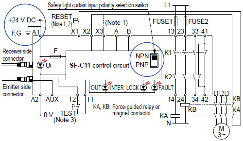
SF-C11
SF2B series wiring diagram (Control category 2)
| For NPN output (plus ground) |
- Set the safety light curtain input polarity selection switch to the NPN side and ground the + side.
Notes:
| 1) |
The above diagram is when using manual reset. If automatic reset is used, disconnect the lead from X2 and connect it to X3. In this case, a reset (RESET) button is not needed. |
| 2) |
Use a momentary-type switch as the reset (RESET) button. |
| 3) |
Emission halt occurs when the test (TEST) button is open, and emission occurs when the test (TEST) button is short-circuited. If not using the test (TEST) button, short-circuit T1 and T2. However, use a test rod or similar to interrupt the light in order to carry out self-diagnosis separately. |
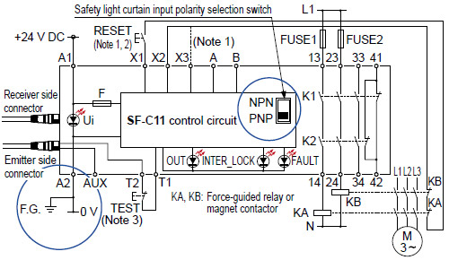
| For PNP output (minus ground) |
- Set the safety light curtain input polarity selection switch to the PNP side and ground the 0 V line.
Notes:
| 1) |
The above diagram is when using manual reset. If automatic reset is used, disconnect the lead from X2 and connect it to X3. In this case, a reset (RESET) button is not needed. |
| 2) |
Use a momentary-type switch as the reset (RESET) button. |
| 3) |
Emission halt occurs when the test (TEST) button is open, and emission occurs when the test (TEST) button is short-circuited. If not using the test (TEST) button, short-circuit T1 and T2. However, use a test rod or similar to interrupt the light in order to carry out self-diagnosis separately. |
Be sure to use the following mating cables when connecting SF-C11 to
SF2B series.
SF2B-CB05 (cable length: 0.5 m 1.640 ft)
SF2B-CB5 (cable length: 5 m 16.404 ft)
SF2B-CB10 (cable length: 10 m 32.808 ft)
SFB-CCJ10E (for emitter, cable length: 10 m 32.808 ft)
SFB-CCJ10D (for receiver, cable length: 10 m 32.808 ft)
|
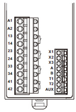
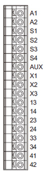
Terminal arrangement diagram
|
|
| Terminal |
Function |
| A1 |
+24 V DC |
| A2 |
0 V |
13-14, 23-24,
33-34 |
Safety output
(NO contact × 3) |
| 41-42 |
Auxiliary output (NC contact × 1) |
| X1 |
Reset output terminal |
| X2 |
Reset input terminal (Manual) |
| X3 |
Reset input terminal (Automatic) |
| A |
Not used |
| B |
| T1 |
Test output terminal |
| T2 |
Test input terminal |
| AUX |
Semiconductor auxiliary output |
|
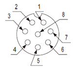
Pin layout for safety light curtain connectors
|
|
| Connector pin No. |
Emitter side connector |
Receiver side connector |
| 1 |
Not used |
OSSD2 |
| 2 |
+24 V DC |
+24 V DC |
| 3 |
Emission halt |
OSSD1 |
| 4 |
Auxiliary output |
EDM (External relay monitor) |
| 5 |
Synchronization wire + |
Synchronization wire + |
| 6 |
Synchronization wire – |
Synchronization wire – |
| 7 |
0 V |
0 V |
| 8 |
Shield wire |
Shield wire |
|
SF-C13
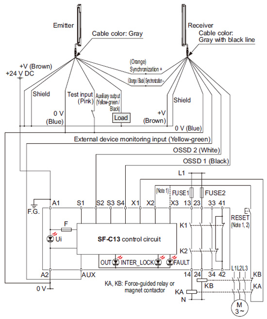
SF2B series wiring diagram (Control category 2)
- Connect the safety light curtain control outputs OSSD 1 and OSSD 2 to S4 and S2 respectively and ground the + side.
Notes:
| 1) |
The left diagram is when using manual reset. If automatic reset is used, disconnect the lead from X2 and connect it to X3. In this case, a reset (RESET) button is not needed. |
| 2) |
Use a momentary-type switch as the reset (RESET) button. |
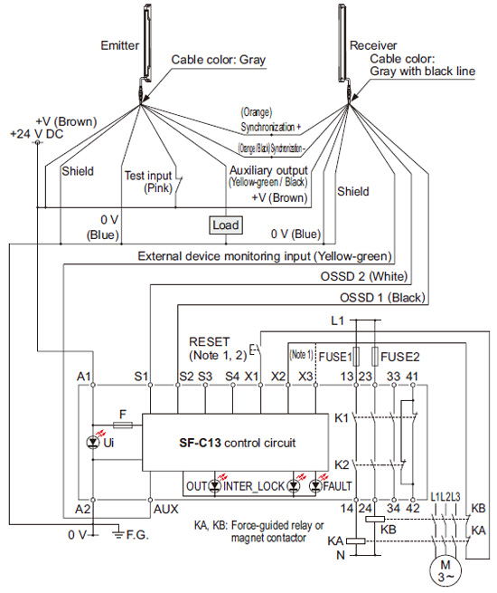
- Connect the safety light curtain control outputs OSSD 1 and OSSD 2 to S1 and S2 respectively.
Notes:
| 1) |
The left diagram is when using manual reset. If automatic reset is used, disconnect the lead from X2 and connect it to X3. In this case, a reset (RESET) button is not needed. |
| 2) |
Use a momentary-type switch as the reset (RESET) button. |
Terminal arrangement diagram
|
|
| Terminal |
Function |
| A1 |
+24 V DC |
| A2 |
0 V |
| S1 to S4 |
Safety light curtain control output
(OSSD) input terminal |
| AUX |
Semiconductor auxiliary output |
| X1 |
Reset output terminal |
| X2 |
Reset input terminal (Manual) |
| X3 |
Reset input terminal (Automatic) |
13-14, 23-24,
33-34 |
Safety output
(NO contact × 3) |
| 41-42 |
Auxiliary output (NC contact × 1) |
|
| |
Use a separate terminal block to carry out wiring for
safety light curtains that cannot be connected to the SF-C13. |
|
Return to top
Return to top

 Business
> Industrial Devices
> Automation Controls Top
> FA Sensors & Components
> Sensors
> Light Curtains / Safety Components
> Safety Light Curtain Type 2 SF2B Ver.2(Discontinued Products)
> I/O Circuit and Wiring diagrams
Business
> Industrial Devices
> Automation Controls Top
> FA Sensors & Components
> Sensors
> Light Curtains / Safety Components
> Safety Light Curtain Type 2 SF2B Ver.2(Discontinued Products)
> I/O Circuit and Wiring diagrams