[System Maintenance Notice]
Due to ongoing system maintenance, the site search and specification search functions are temporarily unavailable. We apologize for any inconvenience this may cause and appreciate your understanding.

 Business
> Industrial Devices
> Automation Controls Top
> FA Sensors & Components
> Sensors
> Light Curtains / Safety Components
> Exclusive Control Unit for Safety Light Curtain SF-C10
> Part Number
> SF-C13
Business
> Industrial Devices
> Automation Controls Top
> FA Sensors & Components
> Sensors
> Light Curtains / Safety Components
> Exclusive Control Unit for Safety Light Curtain SF-C10
> Part Number
> SF-C13
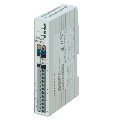
SF-C13 | Exclusive Control Unit for Safety Light Curtain SF-C10


|
*Photo may vary from actual product.

 This product has been confirmed that it does not contain the 6 substances specified in EU RoHS Directive 2011/65/EU and the 4 substances specified in 2015/863/EU.
| Product Number | SF-C13 |
| Part Number | SF-C13 |
| Product | Exclusive Control Unit for Safety Light Curtain |
| Details | Slim type control unit |
| Product name | Exclusive Control Unit for Safety Light Curtain SF-C10 |
As of July 27, 2024
Specifications and design of the products are subject to change without notice for the product improvement.
Spec Detail
| Item | Specifications |
|---|---|
| Product Number | SF-C13 |
| Part Number | SF-C13 |
| Connectable safety light curtains | Safety light curtains manufactured by our company |
| Applicable standards | EN 61496-1 (Type 4), EN 55011, EN ISO 13849-1:2015 (Category 4, , PLe), IEC 61496-1 (Type 4), ISO 13849-1:2015 (Category 4, PLe), JIS B 9704-1 (Type 4), JIS B 9705-1 (Category 4), ANSI/UL 61496-1 (Type 4), UL 1998 (Class 2) |
| Applicable regulations | CE Marking (Machinery Directive, EMC Directive, RoHS Directive),UKCA Marking (Machinery Regulations, EMC Regulations, RoHS Regulations) |
| Power voltage | 24 V DC ±10 % Ripple P-P 10 % or less |
| Current consumption | 100 mA or less (without safety light curtain) |
| Fuse rating | Built-in electronic fuse, Triggering current: 0.5 A or more, Reset after power down |
| Enabling path | NO contact × 3 (13-14, 23-24, 33-34) |
| Enabling path : Utilization | AC-15, DC-13 (IEC 60947-5-1) |
| Enabling path : Rated operation voltage (Ue) / Rated operation current (le) | 30 V DC / 4 A, 230 V AC / 4 A, resistive load(For inductive load, during contact protection)Min. applicable load: 10 mA (at 24 V DC) (Note) : If several SF-C11 or SF-C13 units are being used in a line together, leave a space of 5 mm 0.197 in or more between each unit. |
| Enabling path : Contact material / contacts | Silver tin oxide (AgSnO), self cleaning, positively driven |
| Enabling path : Contact resistance | 100 mOhm or less (initial value) |
| Enabling path : Contact protection fuse rating | 4 A (slow blow) |
| Enabling path : Mechanical lifetime | 10,000,000 times or more (open/close frequency of 180 times/min) (Note:The life expectancy of the relay varies depending on the type of load, open / close frequency, ambient conditions and others.) |
| Enabling path : Electrical lifetime | 100,000 times or more (open/close frequency of 20 times/min, 230 V AC, 3 A, using resistance load) (Note:The life expectancy of the relay varies depending on the type of load, open / close frequency, ambient conditions and others.) |
| Pick-up delay(Auto reset / Manual reset) | 80 ms or less / 90 ms or less |
| Response time | 10 ms or less |
| Auxiliary outputs | Safety relay contact (NC contact) × 1 (41-42) (Related to enabling path) |
| Auxiliary output:Rated operation voltage / current | 24 V DC / 2 A, Min. applicable load: 10 mA (at 24 V DC) |
| Auxiliary output:Contact protection fuse rated | 2 A (slow blow) |
| Semiconductor auxiliary output(AUX) | PNP open‑collector transistor • Maximum source current: 60 mA • Applied voltage: same as supply voltage (between the auxiliary output and +V) • Residual voltage: 2.3 V or less (at 60 mA source current) • Leakage current: 2 mA or less |
| Semiconductor auxiliary output(AUX):Output operation | ON when the safety light curtain is interrupted |
| Excess voltage category | II |
| Indicators:Power supply (Ui) | Green LED (lights up when the power is ON) |
| Indicators : Enabling path (OUT) | Green LED (lights up when the enabling contacts are closed) |
| Indicators:Interlock (INTER_LOCK) | Yellow LED (lights up when enabling contacts are opened) |
| Indicators:Fault (FAULT) | Yellow LED (blinks when fault occurs) |
| External relay monitor function | Incorporated |
| Trailing edge function | Incorporated |
| Polarity selection function | Incorporated (Cable connection allows selection of plus/minus ground) Minus ground: Correspond to PNP output safety light curtain Plus ground: Correspond to NPN output safety light curtain (Note):Please switch the sliding switch to the PNP side for minus ground and to the NPN side for plus ground. |
| Pollution degree | 2 |
| Environmental resistance:Degree of protection | Enclosure: IP40 Terminal: IP20 |
| Environmental resistance:Ambient temperature | -10 to +55 ℃ +14 to +131 ℉ (No dew condensation or icing allowed), Storage: -25 to +70 ℃ -13 to +158℉ |
| Environmental resistance:Ambient humidity | 30 to 85 % RH, Storage: 30 to 95 % RH |
| Environmental resistance:Vibration resistance | Malfunction resistance 10 to 55Hz, 0.35 mm 0.014 in double amplitude 20 times each in X, Y, and Z directions |
| Enclosure material | ABS |
| Connection terminal | Spring-cage terminal |
| Weight | Net weight: 200 g approx. |
Accessories (Option)

|
| Product Number | SFD-CC10 |
| Part Number | SFD-CC10 |
| Product name | Extension Cable |
|
|
| Product Number | SFD-CC10-MU |
| Part Number | SFD-CC10-MU |
| Product name | Extension Cable |
|
|
| Product Number | SFD-CC10-S |
| Part Number | SFD-CC10-S |
| Product name | Extension Cable |
Applicable Products
BY EMAIL


Requests to customers (Automation Control Components & Industrial Device) [Excluding specific product]
Requests to customers (Automation Control Components & Industrial Device) [For specific product]
Requests to customers (FA Sensors & Components [Excluding motors])
Requests to customers (Dedicated to industrial motors)
- COMPONENTS & DEVICES
- FA SENSORS & COMPONENTS
- Fiber Sensors
- Photoelectric Sensors / Laser Sensors
- Micro Photoelectric Sensors
- Light Curtains / Safety Components
- Area Sensors
- Inductive Proximity Sensors
- Particular Use Sensors
- Sensor Options
- Wire-Saving Systems
- Programmable Controllers / Interface Terminal
- Human Machine Interface
- Pressure Sensors / Flow Sensors
- Measurement Sensors
- Static Control Devices
- Laser Markers / 2D Code Readers
- Machine Vision System
- Energy Management Solutions
- Timers / Counters / FA Components
- MOTORS
![]()