[System Maintenance Notice]
Due to ongoing system maintenance, the site search and specification search functions are temporarily unavailable. We apologize for any inconvenience this may cause and appreciate your understanding.

 Business
> Industrial Devices
> Automation Controls Top
> FA Sensors & Components
> Sensors
> Light Curtains / Safety Components
> Ultra-slim Safety door switch with solenoid interlock SG-B1
> Part Number
> SG-B1-MA-G1
Business
> Industrial Devices
> Automation Controls Top
> FA Sensors & Components
> Sensors
> Light Curtains / Safety Components
> Ultra-slim Safety door switch with solenoid interlock SG-B1
> Part Number
> SG-B1-MA-G1
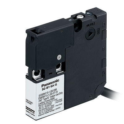
SG-B1-MA-G1 | Ultra-slim Safety door switch with solenoid interlock SG-B1


|
*Photo may vary from actual product.

 This product has been confirmed that it does not contain the 6 substances specified in EU RoHS Directive 2011/65/EU and the 4 substances specified in 2015/863/EU.
| Product Number | SG-B1-MA-G1 |
| Part Number | SG-B1-MA-G1 |
| Product | Ultra-slim Safety door switch with solenoid interlock |
| Details | Magnet lock type |
| Product name | Ultra-slim Safety door switch with solenoid interlock SG-B1 |
As of July 27, 2024
Specifications and design of the products are subject to change without notice for the product improvement.
Spec Detail
| Item | Specifications | |||||||||||||||||||||||||||||||||||||||||||||||||||||
|---|---|---|---|---|---|---|---|---|---|---|---|---|---|---|---|---|---|---|---|---|---|---|---|---|---|---|---|---|---|---|---|---|---|---|---|---|---|---|---|---|---|---|---|---|---|---|---|---|---|---|---|---|---|---|
| Product Number | SG-B1-MA-G1 | |||||||||||||||||||||||||||||||||||||||||||||||||||||
| Part Number | SG-B1-MA-G1 | |||||||||||||||||||||||||||||||||||||||||||||||||||||
| Main contacts | 1NC + 1NC | |||||||||||||||||||||||||||||||||||||||||||||||||||||
| Door monitor contacts | 2NC | |||||||||||||||||||||||||||||||||||||||||||||||||||||
| Lock monitor contacts | 1NC | |||||||||||||||||||||||||||||||||||||||||||||||||||||
| Cable length | 1m 3.281 ft | |||||||||||||||||||||||||||||||||||||||||||||||||||||
| Applicable standards | EN 60947-5-1, GS-ET-19 | |||||||||||||||||||||||||||||||||||||||||||||||||||||
| Applicable standards : Standards for use | IEC 60204-1 / EN 60204-1, ISO 14119, EN ISO 14119, IEC 60947-5-1, UL 508, CSA C22.2 No.14 | |||||||||||||||||||||||||||||||||||||||||||||||||||||
| Applicable regulations | CE Marking [Machinery Directive (2006/42/EC), RoHS Directive], UKCA Marking [Supply of Machinery (Safety) Regulations (2008 No.1597), RoHS Regulations] | |||||||||||||||||||||||||||||||||||||||||||||||||||||
| Operating condition : Ambient temperature | -25 to +50 ℃ -13 to +122 ℉ (No dew condensation or icing allowed) Storage : -40 to +80 ℃ -40 to +176 ℉ |
|||||||||||||||||||||||||||||||||||||||||||||||||||||
| Operating condition : Ambient humidity | 45 to 85 % RH | |||||||||||||||||||||||||||||||||||||||||||||||||||||
| Operating condition : Pollution degree | 3 (Inside 2) | |||||||||||||||||||||||||||||||||||||||||||||||||||||
| Operating condition : Altitude | 2,000 m 6,561.68 ft max. | |||||||||||||||||||||||||||||||||||||||||||||||||||||
| Rated insulation voltage (Ui) | 300 V (Door monitor circuit) 150 V (Main, Lock monitor circuit) 30 V (Between ground and LED, solenoid circuit) |
|||||||||||||||||||||||||||||||||||||||||||||||||||||
| Impulse withstand voltage (Uimp) | 2.5 kV (Door monitor circuit) 1.5 kV (Main, Lock monitor circuit) 0.5 kV (Between ground and LED, solenoid circuit) |
|||||||||||||||||||||||||||||||||||||||||||||||||||||
| Thermal current (Ith) | ・Ambient temperature : -25 to +35 ℃ -13 to +95 ℉ 2.5 A (up to 2 circuits) 1.0 A (3 or more circuits) ・Ambient temperature : 35 to +50 ℃ 95 to +122 ℉ 1.0 A (1 circuit) 0.5 A (2 or more circuits) |
|||||||||||||||||||||||||||||||||||||||||||||||||||||
| Rated operational voltage (Ue) / Rated operational current (Ie) |
|
|||||||||||||||||||||||||||||||||||||||||||||||||||||
| Electric shock protection class | Class II (IEC 61140)(Note), 回(double insulated) (Note): Basic insulation of 2.5 kV, 1.5 kV impulse withstand voltage is ensured between different contact circuits and between contact circuits and LED or solenoid in the enclosure. When both SELV (safety extra low voltage) or PELV (protective extra low voltage) circuits and other circuits (such as 230 V AC circuits) are used for the solenoid power and contact circuits at the same time, the SELV or PELV requirements are not met any more. |
|||||||||||||||||||||||||||||||||||||||||||||||||||||
| Operating frequency | 900 operations/hour | |||||||||||||||||||||||||||||||||||||||||||||||||||||
| Actuator operating speed | 0.05 to 1.0 m/sec. | |||||||||||||||||||||||||||||||||||||||||||||||||||||
| B10D | 2,000,000 (ISO 13849-1 Annex C Table C.1) |
|||||||||||||||||||||||||||||||||||||||||||||||||||||
| Mechanical durability | 1,000,000 operations min. (GS-ET-19) | |||||||||||||||||||||||||||||||||||||||||||||||||||||
| Electrical durability | 100,000 operations min. (900 operations/hour, AC-12 125 V 2A, DC-12 125 V 0.4 A) 1,000,000 operations min. (900 operations/hour, 24 V AC/DC 0.1 A resistive load) |
|||||||||||||||||||||||||||||||||||||||||||||||||||||
| Interlock force | 500 N min. (GS-ET-19) (Note): The actuator locking strength is rated at 500 N of static load. Do not apply a load higher than the rated value. Do not apply a load higher than the rated value. When a higher load is expected to work on the actuator, provide an additional system consisting of another safety switch without lock (such as the SG-A1 safety switch) or a sensor to detect door opening and stop the machine. |
|||||||||||||||||||||||||||||||||||||||||||||||||||||
| Direct opening travel | 8 mm 0.315 in min. | |||||||||||||||||||||||||||||||||||||||||||||||||||||
| Direct opening force | 60 N min. | |||||||||||||||||||||||||||||||||||||||||||||||||||||
| Contact resistance | 300 mΩ max. (initial value, 1 m 3.281 ft cable) 700 mΩ max. (initial value, 5 m 16.404 ft cable) |
|||||||||||||||||||||||||||||||||||||||||||||||||||||
| Protection | IP 67 (IEC 60529) | |||||||||||||||||||||||||||||||||||||||||||||||||||||
| Shock resistance | Malfunction : 100 m/s2, Destruction : 1,000 m/s2 | |||||||||||||||||||||||||||||||||||||||||||||||||||||
| Vibration resistance | Malfunction : 10 to 55 Hz, half amplitude 0.35 mm 0.014 in Destruction : 30 Hz, half amplitude 1.5 mm 0.059 in |
|||||||||||||||||||||||||||||||||||||||||||||||||||||
| Short-circuit protective device | Use 250 V / 10 A fast acting type fuse | |||||||||||||||||||||||||||||||||||||||||||||||||||||
| Material | Enclosure : PA66 | |||||||||||||||||||||||||||||||||||||||||||||||||||||
| Cable | UL style 2464, No.22 AWG 12-core | |||||||||||||||||||||||||||||||||||||||||||||||||||||
| Solenoid / Indicator : Rated operating voltage | DC 24 V 100% duty cycle | |||||||||||||||||||||||||||||||||||||||||||||||||||||
| Solenoid / Indicator : Rated current | 110 mA (solenoid 100 mA, LED 10 mA : initial value) | |||||||||||||||||||||||||||||||||||||||||||||||||||||
| Solenoid / Indicator : Turn on voltage | Rated voltage × 85 % max. (at 20 ℃ 68 ℉) | |||||||||||||||||||||||||||||||||||||||||||||||||||||
| Solenoid / Indicator : Turn off voltage | Rated voltage × 10 % min. (at 20 ℃ 68 ℉) | |||||||||||||||||||||||||||||||||||||||||||||||||||||
| Solenoid / Indicator : Indicator | Green LED | |||||||||||||||||||||||||||||||||||||||||||||||||||||
| Weight | Approx. 220 g | |||||||||||||||||||||||||||||||||||||||||||||||||||||
Accessories (Option)

BY EMAIL


Requests to customers (Automation Control Components & Industrial Device) [Excluding specific product]
Requests to customers (Automation Control Components & Industrial Device) [For specific product]
Requests to customers (FA Sensors & Components [Excluding motors])
Requests to customers (Dedicated to industrial motors)
- COMPONENTS & DEVICES
- FA SENSORS & COMPONENTS
- Fiber Sensors
- Photoelectric Sensors / Laser Sensors
- Micro Photoelectric Sensors
- Light Curtains / Safety Components
- Area Sensors
- Inductive Proximity Sensors
- Particular Use Sensors
- Sensor Options
- Wire-Saving Systems
- Programmable Controllers / Interface Terminal
- Human Machine Interface
- Pressure Sensors / Flow Sensors
- Measurement Sensors
- Static Control Devices
- Laser Markers / 2D Code Readers
- Machine Vision System
- Energy Management Solutions
- Timers / Counters / FA Components
- MOTORS
![]()