[System Maintenance Notice]
Due to ongoing system maintenance, the site search and specification search functions are temporarily unavailable. We apologize for any inconvenience this may cause and appreciate your understanding.

 Business
> Industrial Devices
> Automation Controls Top
> FA Sensors & Components
> Sensors
> Light Curtains / Safety Components
> Compact Type 4 Safety Beam Sensor ST4
> Part Number
> ST4-C12EX
Business
> Industrial Devices
> Automation Controls Top
> FA Sensors & Components
> Sensors
> Light Curtains / Safety Components
> Compact Type 4 Safety Beam Sensor ST4
> Part Number
> ST4-C12EX
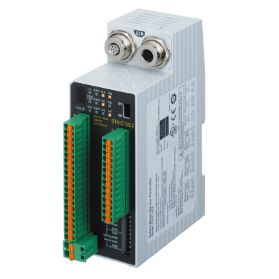
ST4-C12EX | Compact Type 4 Safety Beam Sensor ST4


|
*Photo may vary from actual product.

 This product has been confirmed that it does not contain the 6 substances specified in EU RoHS Directive 2011/65/EU and the 4 substances specified in 2015/863/EU.
| Product Number | ST4-C12EX |
| Part Number | ST4-C12EX |
| Product | Compact Type 4 Safety Beam Sensor |
| Details | Controller [High-functional] |
| Product name | Compact Type 4 Safety Beam Sensor ST4 |
As of July 27, 2024
Specifications and design of the products are subject to change without notice for the product improvement.
Spec Detail
| Item | Specifications |
|---|---|
| Product Number | ST4-C12EX |
| Part Number | ST4-C12EX |
| Applicable standards | IEC 61496-1/2 (JIS B 9704-1/2 / UL 61496-1/2) (Type 4), ISO 13849-1:2015 (Category 4, PLe), JIS B 9705-1 (Category 4), IEC 61508-1 to 3 (SIL3), IEC 62061 (SIL3), JIS C 0508-1 to 3 (SIL3), UL 1998, OSHA 1910.212, OSHA 1910.217 (C), ANSI B11.1 to B11.19, ANSI/RIA R15.06, ANSI/ISA S84.01 (SIL3) (Note) Complies with those standards only when the controller is used in combination with the sensor head ST4-x. |
| CE marking directive compliance | Machinery Directive, EMC Directive, RoHS Directive |
| Power voltage | 24 V DC +10-15 % Ripple P-P 10 % or less |
| Current consumption | 120 mA or less (excluding sensor head ST4-Ax) |
| PFHD | Refer to the following table(Note: (Probability of dangerous failure per hour) depends on number of single beam sensor ST4-A□ connected to controller.) |
| MTTFD | More than 100 years (Note:Mean time to dangerous failure (in years)) |
| Environmental resistance:Degree of protection | Enclosure: IP40 (IEC) Terminal: IP20 (IEC) |
| Environmental resistance:Ambient temperature | -10 to +55 ℃ +14 to +131 ℉ (No dew condensation or icing allowed), Storage: -25 to +70 ℃ -13 to +158 ℉ |
| Environmental resistance:Ambient humidity | 30 to 85 % RH, Storage: 30 to 95 % RH |
| Environmental resistance:Voltage withstandability | 1,000 V AC for one min. between all supply terminals connected together and enclosure |
| Environmental resistance:Insulation resistance | 20 MOhm or more with 500 V DC mega between all supply terminals connected together and enclosure |
| Environmental resistance:Vibration resistance | 10 to 55 Hz frequency, 0.75 mm 0.030 in double amplitude or maximum acceleration 90 m/s2 in X, Y and Z directions for two hours each< |
| Environmental resistance:Shock resistance | 300 m/s2 acceleration in X, Y and Z directions three times each |
| Material | Enclosure: ABS |
| Applicable sensor head | ST4-Ax |
| Applicable sensor head:No. of series connections | Interference prevention possible when up to a maximum of 6 sets are connected(When the maximum of 3 controllers are connected together, interference prevention is possible for up to 18 sets) |
| Control outputs (OSSD 1, OSSD 2) | PNP open-collector transistor / NPN open-collector transistor Dual output x 1 system (Set using output polarity selection switch) [PNP output] Maximum source current: 200 mA Applied voltage: same as the supply voltage (between control output and +V) Residual voltage: 2.5 V or less (at 200 mA source current) Leakage current: 200 micro A or less (including power OFF condition) Maximum load capacity: 1 micro F (from no-load to max. source current) Load wiring resistance: 3 Ohm or less (between control output and load) [NPN output] Maximum sink current: 200 mA Applied voltage: same as the supply voltage (between control output and 0 V) Residual voltage: 2.0 V or less (at 200 mA sink current) Leakage current: 200 micro A or less (including power OFF condition) Maximum load capacity: 1 micro F (from no-load to max. sink current) Load wiring resistance: 3 Ohm or less (between control output and load) (Note) If the total current of the control outputs (OSSD1, OSSD2), auxiliary outputs, and muting lamp output exceeds 400 mA, the wiring resistance between the controller and the power supply should be 1 Ohm or less. In addition, if the total current is 400 mA or less, the wiring resistance between the controller and the power supply should be 2 Ohm or less. |
| Control outputs (OSSD 1, OSSD 2):Operation mode | ON when all beams of the connected ST4-Axs are received OFF when one or more beams of the connected ST4-Axs are interrupted(except during muting / override) OFF during lockout |
| Control outputs(OSSD1, OSSD2):Protection circuit | Incorporated |
| Response time | OFF response: 25 ms or less ON response: 90 ms or less (auto reset) / 140 ms or less (manual reset) |
| Auxiliary outputs | PNP open-collector transistor / NPN open-collector transistor (Set using output polarity selection switch) ST4-C11: one output ST4-C12EX: four outputs [PNP output] Maximum source current: 100 mA Applied voltage: same as the supply voltage (between auxiliary output and +V) Residual voltage: 2.5 V or less (at 100 mA source current) [NPN output] Maximum sink current: 100 mA Applied voltage: same as the supply voltage (between auxiliary output and 0 V) Residual voltage: 2.0 V or less (at 100 mA sink current) (Note) If the total current of the control outputs (OSSD1, OSSD2), auxiliary outputs, and muting lamp output exceeds 400 mA, the wiring resistance between the controller and the power supply should be 1 Ohm or less. In addition, if the total current is 400 mA or less, the wiring resistance between the controller and the power supply should be 2 Ohm or less. |
| Auxiliary outputs:Operation mode | ON when muting function is invalid OFF when muting function is valid ON when override function is invalid OFF when override function is valid ON when muting lamp is in normal condition OFF when muting lamp is in abnormal condition Negative logic of the control outputs (OSSD1, OSSD2) |
| Auxiliary outputs:Protection circuit | Incorporated |
| Muting lamp output | Available muting lamp: 24 V DC, 1 to 10 W (Note) If the total current of the control outputs (OSSD1, OSSD2), auxiliary outputs, and muting lamp output exceeds 400 mA, the wiring resistance between the controller and the power supply should be 1 Ohm or less. In addition, if the total current is 400 mA or less, the wiring resistance between the controller and the power supply should be 2 Ohm or less. |
| Muting lamp output:Protection circuit | Incorporated |
| Connection terminal | Detachable spring-cage terminal |
| Wiring cable | Terminal block connector: 0.2 to 1.5 mm2 Power supply connector (A1, A2): 0.2 to 2.5 mm2 |
| Weight | Net weight: 240 g approx Gross weight: 450 g approx |
BY EMAIL


Requests to customers (Automation Control Components & Industrial Device) [Excluding specific product]
Requests to customers (Automation Control Components & Industrial Device) [For specific product]
Requests to customers (FA Sensors & Components [Excluding motors])
Requests to customers (Dedicated to industrial motors)
- COMPONENTS & DEVICES
- FA SENSORS & COMPONENTS
- Fiber Sensors
- Photoelectric Sensors / Laser Sensors
- Micro Photoelectric Sensors
- Light Curtains / Safety Components
- Area Sensors
- Inductive Proximity Sensors
- Particular Use Sensors
- Sensor Options
- Wire-Saving Systems
- Programmable Controllers / Interface Terminal
- Human Machine Interface
- Pressure Sensors / Flow Sensors
- Measurement Sensors
- Static Control Devices
- Laser Markers / 2D Code Readers
- Machine Vision System
- Energy Management Solutions
- Timers / Counters / FA Components
- MOTORS
![]()