[System Maintenance Notice]
Due to ongoing system maintenance, the site search and specification search functions are temporarily unavailable. We apologize for any inconvenience this may cause and appreciate your understanding.
【Notification of Manufacturer Change for Panasonic Industrial Devices SUNX Products and Panasonic Industrial Devices SUNX Tatsuno Products】
From April 1, 2024, the terms "Panasonic Industrial Devices SUNX Co., Ltd." and "Panasonic Industrial Devices SUNX Tatsuno Co., Ltd."
in this page and in the manuals and other documents to be downloaded will all be replaced with "Panasonic Industry Co., Ltd." and applied accordingly.

 Business
> Industrial Devices
> Automation Controls Top
> FA Sensors & Components
> Timers / Counters / FA Componets
> Counters
> Counters Technical Terminology
Business
> Industrial Devices
> Automation Controls Top
> FA Sensors & Components
> Timers / Counters / FA Componets
> Counters
> Counters Technical Terminology
Counters Technical Terminology
TYPES OF COUNTERS
Electro Preset Counter
The counter is equipped with semiconductor counting circuitry. When the counter counts up to a preset number, its output circuit sends a signal.
Electro Magnetic Counter
A magnet is magnetized and demagnetized to drive the dial and count up numbers.
RATING
Rated Operational Voltage
The voltage is applied to start the counter.
COUNTINGS
1.Pulse
This is a voltage or current signal sent at intermittent time intervals.
2.Count
Pulses are used to count up and down.
3.Mis-count
This happens if the number of pulses does not correspond to the number of counts.
4.Hertz
This unit of counting speed is used to give the number of counts per second. This unit of counting speed is used to give the number of counts per second.
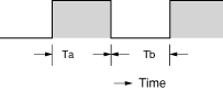
5.Make Ratio
This is the ratio of ON time (Ta) to OFF time (Tb).
|
6.Maximum Counting Speed
Suppose that the counter is operated with an input pulse of a make ratio of 1. The highest counting speed is the peak of a range in which the output circuit can send signals without mis-counting. The speed is expressed in units of Hz (cps: counts per second).
7.Over Count
Counting continues beyond a preset number.
8.Recount
When counting is up, the counter display resets to zero and counting restarts.
9.Down Count
Numbers are counted down one by one from a preset number.
10.Up Count
Numbers are counted up one by one from zero.
11.Up/Down Count
Numbers are counted up or down depending on input conditions.
12.Rejection (gate) Input
This signal is used to keep the counter from counting.
OUTPUTS
1.Count Up
When a preset number is reached, the output circuit sends a signal.
2.Retained Output
The output is held until a reset signal is sent.
3.One Shot Output
This output has a specified width of time.
RESETTINGS
1.Reset
The counting process, display and output sections are all brought back to the initial status.
2.Power off Reset
The operating voltage is turned off to reset the counter.
3.Manual Reset
The counter is manually reset.
4.Remote Reset
A signal is sent from a remote point to the reset terminal so as to reset the counter.
5.Automatic Reset
When counting is up, internal circuitry is activated to automatically reset the counter.
6.Reset Signal Width
This is the time during which the power is off so as to reset the counter or during which an external (manual) reset signal is sent.
7.Reset time
This is the time from the moment a reset signal is sent to the instant the counter is ready to start counting again.
Others
1.Function of Memorizing Condition
Counting data up until the operating voltage is turned off can be stored in memory. When the power is reactivated, the data can be reproduced.
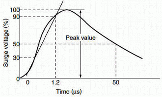
2.Anti-surge
The strength against power voltage surge is determined by applying a singlepole full-wave voltage (several hundred to several thousand volt wave for ±(1.2 × 50) μs) acrosss the control power terminals.
|
3.Noise Immunity
This is the strength against external noise. Relay noise tests, noise simulator tests, etc. are conducted.
BY EMAIL
- U.S.A.
- +1-800-344-2112
- Europe
- +49-89-45354-1000
- China
- +86-10-59255988
- Singapore
- +65-6299-9181


Requests to customers (Automation Control Components & Industrial Device) [Excluding specific product]
Requests to customers (Automation Control Components & Industrial Device) [For specific product]
Requests to customers (FA Sensors & Components [Excluding motors])
Requests to customers (Dedicated to industrial motors)
- COMPONENTS & DEVICES
- FA SENSORS & COMPONENTS
- Fiber Sensors
- Photoelectric Sensors / Laser Sensors
- Micro Photoelectric Sensors
- Light Curtains / Safety Components
- Area Sensors
- Inductive Proximity Sensors
- Particular Use Sensors
- Sensor Options
- Wire-Saving Systems
- Programmable Controllers / Interface Terminal
- Human Machine Interface
- Pressure Sensors / Flow Sensors
- Measurement Sensors
- Static Control Devices
- Laser Markers / 2D Code Readers
- Machine Vision System
- Energy Management Solutions
- Timers / Counters / FA Components
- MOTORS
![]()