【Notification of Manufacturer Change for Panasonic Industrial Devices SUNX Products and Panasonic Industrial Devices SUNX Tatsuno Products】
From April 1, 2024, the terms "Panasonic Industrial Devices SUNX Co., Ltd." and "Panasonic Industrial Devices SUNX Tatsuno Co., Ltd."
in this page and in the manuals and other documents to be downloaded will all be replaced with "Panasonic Industry Co., Ltd." and applied accordingly.

 Business
> Industrial Devices
> Automation Controls Top
> FA Sensors & Components
> Measurement Sensors
> Measurement Sensors
> Metal-sheet Double-feed Detector GD(Discontinued Products)
> Cautions For Use
Business
> Industrial Devices
> Automation Controls Top
> FA Sensors & Components
> Measurement Sensors
> Measurement Sensors
> Metal-sheet Double-feed Detector GD(Discontinued Products)
> Cautions For Use
Metal-sheet Double-feed Detector GD (Discontinued Products)
|
We are sorry, the products have been discontinued. Please refer to the details of the discontinued products and the recommended substitutes list below.
|
Cautions For Use
- Never use this product as a sensing device for personnel protection.
- In case of using sensing devices for personnel protection, use products which meet laws and standards, such as OSHA, ANSI or IEC etc., for personnel protection applicable in each region or country.
- Make sure to use the sensor heads and controllers in the specified combinations. If they are used in any other combination, the sensor heads may get damaged.
Mounting
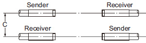
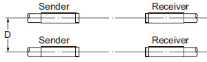
Placing of sensor heads
- Make the sender and receiver face each other and align their sensing center line.
|
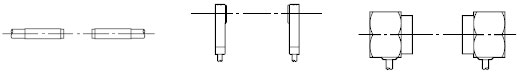
- Keep a distance from any magnet or a device generating magnetic field. It may degrade the detectability.
- Surrounding metal influences the detectability. Please contact our office for more details.
- If more than one set of sensor heads are closely mounted, detectability may be affected. Please contact our office for more details.
Mounting sensor heads
|
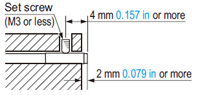
- Use a set screw (M3 or less), and the tightening torque should be 0.12 N·m or less.
|
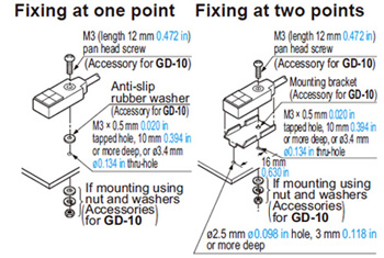
- The tightening torque should be 0.5 N·m or less.
- To mount the sensor head with a nut, the thru-hole should be ø3.4 mm ø0.134 in.
(The mounting board must be 2.3 mm 0.091 in, or less, thick.)
|
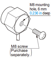
- The tightening torque should be 11.2 N·m or less.
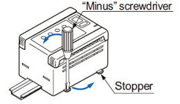
Mounting of controller
<On DIN rail> |
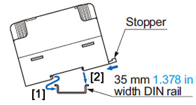 |
[2] Press and fit the rear portion of the mounting section on the 35 mm 1.378 in width DIN rail. |
 |
<On board with screws>
|
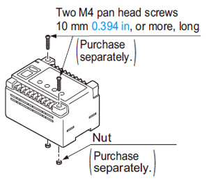 |
Sensing mode
- The GD series has two sensing modes, one is the normal sensing mode and the other is the precise sensing mode. They are automatically selected by the characteristics of the object.
 |
Normal sensing mode: |
 |
Precise sensing mode: |
- The sensing mode indicator lights up green during the normal sensing mode, but lights up yellow during the precise sensing mode.
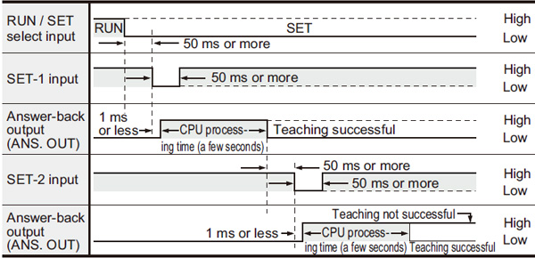
Sensitivity setting
- Teaching by external input
|
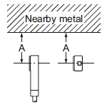
Distance from nearby metals
- As metals near the sensor head may affect the sensing performance, pay attention to the following points.
Influence of nearby metal
- The sensor head must be separated from nearby metal by a minimum distance as specified in the table below.
|
|
|
|||||||||
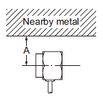
| Setting distance | 5mm 0.197 in |
10mm 0.394 in |
30mm 1.181 in |
70mm 2.756 in |
|---|---|---|---|---|
| GD-3 | 15mm 0.591 in |
20mm 0.787 in |
── | ── |
| GD-10 | 100mm 3.937 in |
── | ||
| GD-20 | 100mm 3.937 in |
|||
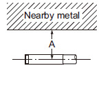
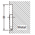
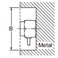
Embedding in metal
- The sensing performance may be affected if the sensor is completely embedded in a metal. Keep a minimum clearance between the sensor head and the metal as specified in the table below.
|
|
|
|||||||||
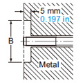
| Setting distance | 5mm 0.197 in |
10mm 0.394 in |
30mm 1.181 in |
70mm 2.756 in |
|---|---|---|---|---|
| GD-3 | ø15mm ø0.591 in |
ø20mm ø0.787 in |
── | ── |
| GD-10 | ø100mm ø3.937 in |
── | ||
| GD-20 | ø300mm ø11.811 in |
|||
Interference prevention
- When two or more sensor heads are mounted in parallel, keep a minimum separation distance as specified below to avoid interference.
|
| Setting distance(Note) | 5mm 0.197 in |
10mm 0.394 in |
20(35)mm 0.787 (1.378) in |
30(70)mm 1.181 (2.756) in |
|---|---|---|---|---|
| GD-3 | 60mm 2.362 in |
80mm 3.150 in |
── | ── |
| GD-10 | 160mm 6.299 in |
220mm 8.661 in |
||
| GD-20 | 370mm 14.567 in |
630mm 24.803 in |
||
| Note: | The value in the brackets is for GD-20. |
|---|
|
| Setting distance(Note) | 5mm 0.197 in |
10mm 0.394 in |
20(35)mm 0.787 (1.378) in |
30(70)mm 1.181 (2.756) in |
|---|---|---|---|---|
| GD-3 | 30mm 1.181 in |
50mm 1.969 in |
── | ── |
| GD-10 | 200mm 7.874 in |
250mm 9.843 in |
||
| GD-20 | 450mm 17.717 in |
700mm 27.559 in |
||
| Note: | The value in the brackets is for GD-20. |
|---|
RS-232C data transmission (GD-C2 only)
- GD-C2 can feed in the set level data into a PC or PLC memory using RS-232C serial communication and retrieve it whenever required. In this case, the taught data should be stored in the prescribed channel.
Transmission specifications
- Baud rate: Selectable from 300, 600, 1,200, 2,400, 4,800, 9,600, 19,200, 31,250 bits/sec.
- Format: Data bits・・・7 bits or 8 bits
Parity check・・・None or Enable, Even or Odd
Stop bits・・・1 bit or 2 bits
Terminal code・・・CR or ETX
Self-diagnosis (Alarm) function
- The GD series constantly runs self-diagnosis, outputs the result with self-diagnosis output, and lights the selfdiagnosis indicator. In addition, error content is shown on the channel display using error codes.
Others
| ・Do not operate the sensor for a few seconds immediately after supplying power because of transient conditions including self-diagnosis time. |
- Make sure to check the ability of the sensor to detect the number of sheets of your actual objects before use. If real objects differ from teaching samples in size or in characteristics, or the detecting condition deviates, an error may occur. Please note that magnetic metals or metals with low magnetic permeability such as steel especially have a strong tendency.
- In situations when magnets are in close proximity such as during electromagnet conveyance, this causes malfunctions due to electromagnetic disorder.
- When conducting minute detections, favorable sensing conditions are obtained only after having elapsed 60 min. after the initial introduction of the power supply.
BY EMAIL
- U.S.A.
- +1-800-344-2112
- Europe
- +49-89-45354-1000
- China
- +86-10-59255988
- Singapore
- +65-6299-9181


Requests to customers (Automation Control Components & Industrial Device) [Excluding specific product]
Requests to customers (Automation Control Components & Industrial Device) [For specific product]
Requests to customers (FA Sensors & Components [Excluding motors])
Requests to customers (Dedicated to industrial motors)
- COMPONENTS & DEVICES
- FA SENSORS & COMPONENTS
- Fiber Sensors
- Photoelectric Sensors / Laser Sensors
- Micro Photoelectric Sensors
- Light Curtains / Safety Components
- Area Sensors
- Inductive Proximity Sensors
- Particular Use Sensors
- Sensor Options
- Wire-Saving Systems
- Programmable Controllers / Interface Terminal
- Human Machine Interface
- Pressure Sensors / Flow Sensors
- Measurement Sensors
- Static Control Devices
- Laser Markers / 2D Code Readers
- Machine Vision System
- Energy Management Solutions
- Timers / Counters / FA Components
- MOTORS
![]()