[System Maintenance Notice]
Due to ongoing system maintenance, the site search and specification search functions are temporarily unavailable. We apologize for any inconvenience this may cause and appreciate your understanding.
【Notification of Manufacturer Change for Panasonic Industrial Devices SUNX Products and Panasonic Industrial Devices SUNX Tatsuno Products】
From April 1, 2024, the terms "Panasonic Industrial Devices SUNX Co., Ltd." and "Panasonic Industrial Devices SUNX Tatsuno Co., Ltd."
in this page and in the manuals and other documents to be downloaded will all be replaced with "Panasonic Industry Co., Ltd." and applied accordingly.
High Accuracy Eddy Current Type Displacement Sensor GP-A (Discontinued Products)
We are sorry, the products have been discontinued. Please refer to the details of the discontinued products and the recommended substitutes list below.
 |
September 30, 2018 |
|
|
I/O Circuit and Wiring diagrams
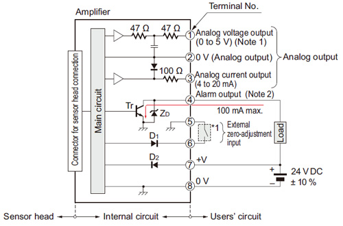
I/O circuit diagram
Notes:
| 1) |
In case of using the analog voltage output, connect a device having a high input impedance. Also, take care that the output voltage is reduced due to the resistance of the wiring cable. |
| 2) |
The alarm output is not incorporated with a short-circuit protection circuit. Do not connect it directly to a power supply or a capacitive load. |
| Symbols・・・ |
D1: Input protection diode
D2: Reverse supply polarity protection diode
ZD: Surge absorption zener diode
Tr : NPN output transistor |
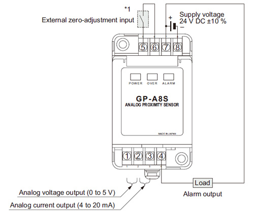
Wiring diagram
| Note: |
After the wiring, make sure to fit the terminal covers. The terminal cover having a concave depression at the top should be fitted on the side having terminal Nos. 1 to 4. |
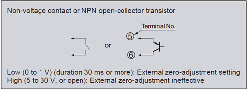
*1 |
 |
|
Return to top
Return to top

 Business
> Industrial Devices
> Automation Controls Top
> FA Sensors & Components
> Measurement Sensors
> Measurement Sensors
> High Accuracy Eddy Current Type Displacement Sensor GP-A(Discontinued Products)
> I/O Circuit and Wiring diagrams
Business
> Industrial Devices
> Automation Controls Top
> FA Sensors & Components
> Measurement Sensors
> Measurement Sensors
> High Accuracy Eddy Current Type Displacement Sensor GP-A(Discontinued Products)
> I/O Circuit and Wiring diagrams