[System Maintenance Notice]
Due to ongoing system maintenance, the site search and specification search functions are temporarily unavailable. We apologize for any inconvenience this may cause and appreciate your understanding.
【Notification of Manufacturer Change for Panasonic Industrial Devices SUNX Products and Panasonic Industrial Devices SUNX Tatsuno Products】
From April 1, 2024, the terms "Panasonic Industrial Devices SUNX Co., Ltd." and "Panasonic Industrial Devices SUNX Tatsuno Co., Ltd."
in this page and in the manuals and other documents to be downloaded will all be replaced with "Panasonic Industry Co., Ltd." and applied accordingly.
High Speed・High Accuracy Eddy Current Type Digital Displacement Sensor GP-X
Cautions For Use
- Never use this product as a sensing device for personnel protection.
- In case of using sensing devices for personnel protection, use products which meet laws and standards, such as OSHA, ANSI or IEC etc., for personnel protection applicable in each region or country.
| ・ |
The sensor head and the controller are adjusted in order to conform to the default specification linearity. |
| ・ |
In the event of replacing sensor heads, input the sensor head’s characteristic code and conduct 3-point correction (calibration). |
| ・ |
Should you use an extension cable, turn the sensor head cable length selection switch located on the back of the controller to “3 m + 7 m 9.843 ft + 22.966 ft”. Then reintroduce the power supply and conduct 3-point correction (calibration). |
Conditions in use for CE/UKCA conformity
- This product is CE/UKCA compliant and complies with EMC directives/EMC regulations. EN 61000-6-2 is the applicable standard that covers immunities relating to use of this product, but in order to comply with this standard, the following conditions must be satisfied.
- The controller should be connected less than 10 m 32.808 ft from the power supply.
- The signal line to connect with the controller should be less than 30 m 98.425 ft.
- A ferrite clamp must be mounted within 10 mm 0.394 in from connector fitted onto the GP-XBCC3 cable with connector on one end for BCD output units.
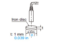
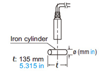
Linearity in case of disc-shaped or cylindrical objects
- In case the sensing object is disc-shaped or cylindrical, the linearity varies with the sensing object size.
In the event the sensing object is larger than the sizes indicated in the table below, the linearity specification (within ±0.3 % F.S.) is satisfied by performing zero-adjustment
and span adjustment when in contact using the scaling function.
|
<In case of disc>
<In case of cylinder>
|
|
| Sensor head |
Disc diameter ø (mm in) |
Cylinder diameter ø (mm in) |
| GP-X3SE |
6 0.236 |
16 0.630 |
| GP-X5SE |
8 0.315 |
16 0.630 |
| GP-X8S |
12 0.472 |
50 1.969 |
| GP-X10M |
12 0.472 |
50 1.969 |
| GP-X12ML |
25 0.984 |
55 2.165 |
| GP-X22KLM |
30 1.181 |
165 6.496 |
|
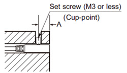
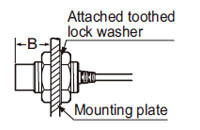
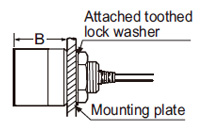
Mounting sensor head
- The tightening torque should be under the value given below.
- Make sure to use an M3 or smaller set screw having a cup-point.
 |
|
| Model No. |
A (mm in) |
Tightening torque |
| GP-X3SE |
4 to 16 0.157 to 0.630 |
0.10 N·m or less |
| GP-X5SE |
5 to 16 0.197 to 0.630 |
0.44 N·m or less |
| GP-X8S |
0.58 N·m or less |
|
| <GP-X10M> |
|---|
 |
|
|
| <GP-X12ML> |
|---|
 |
|
|
| <GP-X22KL> |
|---|
 |
|
|
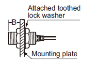
| Model No. |
B (mm in) |
Tightening torque |
| GP-X10M |
7 0.276 or more |
9.8 N·m or less |
| GP-X12ML |
14 0.551 or more |
20 N·m or less |
| GP-X22KL |
20 0.787 or more (Note 1) |
20 N·m or less |
Notes:
| 1) |
Without nut. If a nut is installed, the dimension will be 23.5 mm 0.926 in or more. |
| 2) |
Mount such that the nuts do not protrude from the threaded portion. |
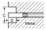
| Distance from surrounding metal |
- As metal around the sensor head may affect the sensing performance, pay attention to the following points.
<Embedding of the sensor head in metal>
- Since the analog output may change if the sensor head is completely embedded in metal, keep the minimum distance specified in the table below.
 |
|
| Sensor head |
C (mm in) |
D (mm in) |
| GP-X3SE |
ø10 ø0.394 |
3 0.118 |
| GP-X5SE |
| GP-X8S |
ø18 ø0.709 |
| GP-X10M |
ø14 ø0.551 |
| GP-X12ML |
ø50 ø1.969 |
14 0.551 |
| GP-X22KL |
ø50 ø1.969 |
20 0.787 |
|
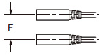
- If several sensor heads are mounted close together, some specifications may not be satisfied. Therefore, proceed with the interference prevention function enabled.
The interference prevention function eliminates interference among sensors by alternating sensor oscillations. Contact our office for details about time charts etc. If not using the interference prevention function, leave a distance more than the values given below.
|
<Face to face mounting>
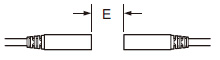
<Parallel mounting>
|
|
| Sensor head |
E (mm in) |
F (mm in) |
| GP-X3SE |
15 0.591 |
9 0.354 |
| GP-X5SE |
30 1.181 |
11 0.433 |
| GP-X8S |
40 1.575 |
15 0.591 |
| GP-X10M |
40 1.575 |
15 0.591 |
| GP-X12ML |
170 6.693 |
50 1.969 |
| GP-X22KL |
200 7.874 |
200 7.874 |
|
Sensing range
- The sensing range is specified for the standard sensing object [stainless steel (SUS304) / iron [Cold rolled carbon steel (SPCC)], 60 × 60 × t 1 mm 2.362 × 2.362 × t 0.039 in]. For sensing metals other than the standard sensing objects, use the correction coefficient stated below as a guideline. Verify with the actual sensor before using.
Correction coefficient
| |
GP-X3SE GP-X5SE GP-X8S
GP-X10M GP-X12ML GP-X22KL |
| Stainless steel (SUS304), Iron |
1 |
| Aluminum |
0.5 approx. |
Others
- After turning on the power, wait 15 min. or more [20 min.for the GP-XC3SE(-P) and GP-XC5SE(-P)] before usingthe product.
The power supply circuit is not stable immediately after the power is turned on, and this may cause measurement values to be distorted. In addition, note that there will also be a muting period of approx. 2 sec.
Return to top
Return to top

 Business
> Industrial Devices
> Automation Controls Top
> FA Sensors & Components
> Measurement Sensors
> Measurement Sensors
> High Speed・High Accuracy Eddy Current Type Digital Displacement Sensor GP-X
> Cautions For Use
Business
> Industrial Devices
> Automation Controls Top
> FA Sensors & Components
> Measurement Sensors
> Measurement Sensors
> High Speed・High Accuracy Eddy Current Type Digital Displacement Sensor GP-X
> Cautions For Use


