[System Maintenance Notice]
Due to ongoing system maintenance, the site search and specification search functions are temporarily unavailable. We apologize for any inconvenience this may cause and appreciate your understanding.
【Notification of Manufacturer Change for Panasonic Industrial Devices SUNX Products and Panasonic Industrial Devices SUNX Tatsuno Products】
From April 1, 2024, the terms "Panasonic Industrial Devices SUNX Co., Ltd." and "Panasonic Industrial Devices SUNX Tatsuno Co., Ltd."
in this page and in the manuals and other documents to be downloaded will all be replaced with "Panasonic Industry Co., Ltd." and applied accordingly.

 Business
> Industrial Devices
> Automation Controls Top
> FA Sensors & Components
> Sensors
> Fiber Sensors
> Digital Fiber Sensor FX-100
> Cautions For Use
Business
> Industrial Devices
> Automation Controls Top
> FA Sensors & Components
> Sensors
> Fiber Sensors
> Digital Fiber Sensor FX-100
> Cautions For Use
Digital Fiber Sensor FX-100
|
Cautions For Use
- Never use this product as a sensing device for personnel protection.
- In case of using sensing devices for personnel protection, use products which meet laws and standards, such as OSHA, ANSI or IEC etc., for personnel protection applicable in each region or country.
Using in combination with the FX-300 / FX-410 series
- The FX-100 series does not use the horizontal connectors that are used with the FX-300 / FX-410 series. Please note that horizontal connection cannot be performed using a connector attached cable. In addition, the optical communication function is not equipped on the FX-100 series, so it is unable to perform interference prevention for use with the FX-300 / FX-410 series.
If using the FX-100 series together with the FX-300 / FX-410 series side-by-side, please set the same models together in groups.
Mounting
<When using a DIN rail>
| How to mount the amplifier |
|---|
|
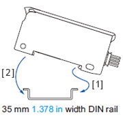 |
| How to remove the amplifier |
|---|
|
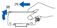
| Note: | Take care that if the front part is lifted without pushing the amplifier forward, the hook on the rear portion of the mounting section is likely to break. |
|---|
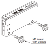
<When using screws with washers>
|
Wiring
- Make sure that the power supply is OFF while adding or removing the amplifiers.
- Note that if a voltage exceeding the reted range is applied, or if an AC power supply is directly connected, the product may get burnt or damaged.
- Note that short-circuit of the load or wrong wiring may burn or damage the product.
- Do not run the wires together with high-voltage lines or power lines, or put them in the same raceway. This can cause malfunction due to induction.
- Verify that the supply voltage variation is within the rating.
- If power is supplied from a commercial switching regulator, ensure that the frame ground (F.G.) terminal of the power supply is connected to an actual ground.
- In case noise generating equipment (switching regulator, inverter motor, etc.) is used in the vicinity of this product, connect the frame ground (F.G.) terminal of the equipment to an actual ground.
- Make sure to use the quick-connection cable (optional) for the connection of the controller.
Extension up to total 100 m 328.084 ft is possible with 0.3 mm2 or more, cable. However, in order to reduce noise, make the wiring as short as possible.
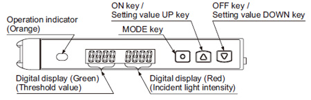
Part description
|
Setting mode
- Setting mode appears after the MODE key is pressed for 2 sec. in RUN mode.
| Setting item | Factory setting | Description |
|---|---|---|
| Teaching mode |  |
Threshold value can be set in 2-point teaching, limit teaching, or full-auto teaching. |
| Output operation setting |  [Dark-ON] |
Light-ON or Dark-ON can be set. |
| Timer operation setting |  [Without timer] |
Without timer, ON delay timer, or OFF delay timer can be set. |
| Timer delays setting |  [ON-delay timer: 10 ms]  [OFF-delay timer: 10 ms] |
When setting ON delay timer or OFF delay timer in the timer operation setting mode, timer delays can be set. ・When timer is not set, this mode is not displayed. |
| Emission amount setting |  *[Level 3] |
In case incident light intensity is saturated, emission amount can be reduced. |
| Emission frequency setting | FX-101□ [0 (Response time:250 μs or less)] FX-102□  [1 (Response time:2.5 ms or less)] |
When using the fiber heads in parallel, interference can be prevented by setting different emission frequency. However, when emission frequency 0 is set, interference cannot be prevented. Response time corresponds to emission frequency. |
 ” before production in November 2007.
PRO mode
- PRO mode appears after the MODE key is pressed for 4 sec. in RUN mode.
| Setting item | Factory setting | Description |
|---|---|---|
| Shift setting |  [Shift amount 15 %] |
Shift amount can be selected from 0 to 80 % in the limit teaching. Select 0 % when it is desired to set the present incident light intensity as a threshold value. |
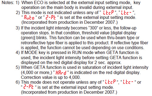
| External input setting |  [Emission halt] |
External input can be selected from emission halt, limit teaching [+], limit teaching [-], full-auto teaching, ECO (Note 1), 2-point teaching or emission amount test. When setting the incident light intensity test “ ”, output turns ON / OFF every 100ms when the rate of incident light intensity and threshold value is less than half of the set shift amount (for example, when the rate of incident light intensity and threshold value is within ±10 % for 20 % of shift amount) at external input. ”, output turns ON / OFF every 100ms when the rate of incident light intensity and threshold value is less than half of the set shift amount (for example, when the rate of incident light intensity and threshold value is within ±10 % for 20 % of shift amount) at external input. |
| Threshold value-storing setting mode (Note 2) |  |
Threshold value set at the limit teaching, full-auto teaching or 2-point teaching by external input is stored. When selecting Auto in the emission amount setting mode, the set emission amount level is also stored. |
| Threshold value follow-up cycle setting (Note 3) |  |
When incident light intensity exceeds threshold value, this mode can change the threshold value with each set cycle depending on variations of the incident light intensity. The follow-up shift amount is same as the one set in the shift setting mode. However, the threshold value is not stored. |
| GETA function setting (Note 4, 5) |  |
Variations can be reduced by correcting the present incident light intensity in each amplifier to a target value. Target value to offset incident light intensity can be selected from 0 to 2,000 by 100 unit each. For example, if the target value is set to 2,000 when the incident light intensity is 1,500, the incident light intensity becomes 2,000. |
| ECO setting |  |
It is possible to light up / turn off the digital display. When ECO setting mode is ON, the display turns off in 20 sec. approx. in RUN mode. To light up the display again, press any key for 2 sec. or more. |
| Digital display inversion setting |  |
Digital display can be inverted. |
| Threshold value margin setting |  |
Margin for threshold value to the present incident light intensity can be checked. When there is no margin, it is possible to make the digital display blink. : Set to “OFF”: does not function : Set to “OFF”: does not function : Green blinks. : Green blinks. : Red blinks. : Red blinks. : Red and green blink. : Red and green blink. : When conducting limit teaching or 2-point teaching by external input, in case the rate of reference incident light intensity and threshold value after teaching is 200% or more, or in case it is less than half of the shift amount, output turns ON / OFF every 100 ms. (Note 6) : When conducting limit teaching or 2-point teaching by external input, in case the rate of reference incident light intensity and threshold value after teaching is 200% or more, or in case it is less than half of the shift amount, output turns ON / OFF every 100 ms. (Note 6) |
| Setting copy |  |
The settings of the master side amplifier can be copied to the slave side amplifier. For details, refer to “Setting copy function”. |
| Reset |  |
Returns to default settings (factory settings.) |
|
Setting copy function
Refer to the "Instruction Manual" for details.
Others
- This product has been developed / produced for industrial use only.
- Do not use during the initial transient time (0.5 sec.) after the power supply is switched on.
- Take care that the product is not directly exposed to fluorescent lamp from a rapid-starter lamp, a high frequency lighting device or sunlight etc., as it may affect the sensing performance.
- This product is suitable for indoor use only.
- Avoid dust, dirt, and steam.
- Take care that the product does not come in contact with oil, grease, organic solvents, such as thinner, etc., strong acid or alkaline.
- This product cannot be used in an environment containing inflammable or explosive gases.
- Never disassemble or modify this product.
- EEPROM is adopted to this product. It is not possible to conduct teaching 100 thousand times or more, because of the EEPROM’s lifetime.
Quick setting function
|
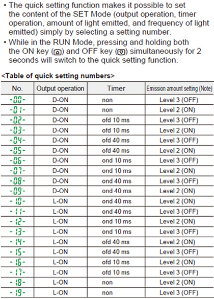
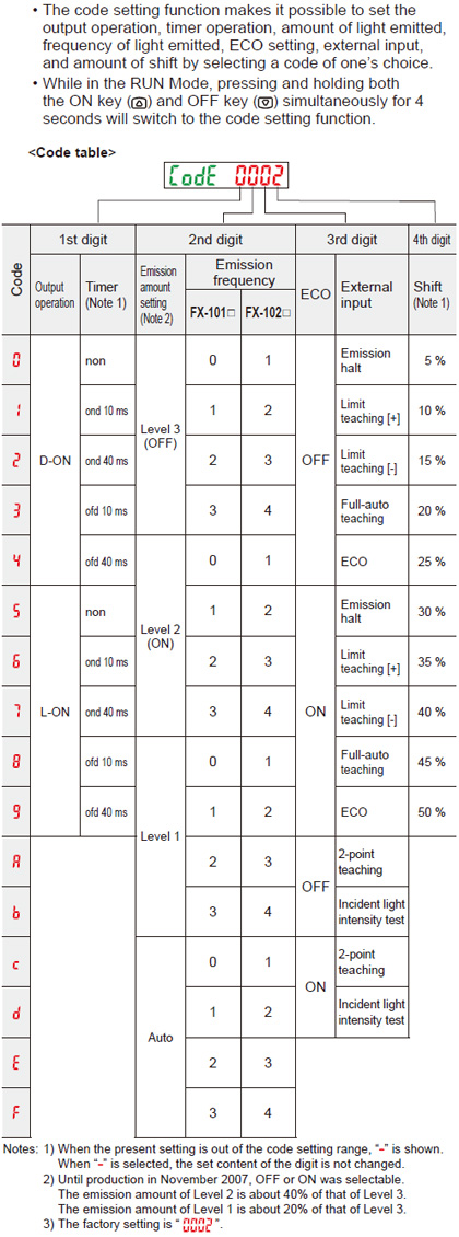
| Note: | Until production in November 2007, OFF or ON was selectable. The emission amount of Level 2 (ON) is about 40% of that of Level 3 (OFF). |
|---|
Difference between previous model and upgraded one
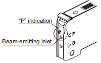
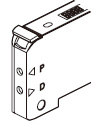
- For upgraded ones (production in and after December 2007), “P” is marked near the beam-emitting inlet.
Previous ones have no marking. Appearance and functions have been changed.
|
|
Code setting function
|
BY EMAIL
- U.S.A.
- +1-800-344-2112
- Europe
- +49-89-45354-1000
- China
- +86-10-59255988
- Singapore
- +65-6299-9181


Requests to customers (Automation Control Components & Industrial Device) [Excluding specific product]
Requests to customers (Automation Control Components & Industrial Device) [For specific product]
Requests to customers (FA Sensors & Components [Excluding motors])
Requests to customers (Dedicated to industrial motors)
- COMPONENTS & DEVICES
- FA SENSORS & COMPONENTS
- Fiber Sensors
- Photoelectric Sensors / Laser Sensors
- Micro Photoelectric Sensors
- Light Curtains / Safety Components
- Area Sensors
- Inductive Proximity Sensors
- Particular Use Sensors
- Sensor Options
- Wire-Saving Systems
- Programmable Controllers / Interface Terminal
- Human Machine Interface
- Pressure Sensors / Flow Sensors
- Measurement Sensors
- Static Control Devices
- Laser Markers / 2D Code Readers
- Machine Vision System
- Energy Management Solutions
- Timers / Counters / FA Components
- MOTORS
![]()