[System Maintenance Notice]
Due to ongoing system maintenance, the site search and specification search functions are temporarily unavailable. We apologize for any inconvenience this may cause and appreciate your understanding.
【Notification of Manufacturer Change for Panasonic Industrial Devices SUNX Products and Panasonic Industrial Devices SUNX Tatsuno Products】
From April 1, 2024, the terms "Panasonic Industrial Devices SUNX Co., Ltd." and "Panasonic Industrial Devices SUNX Tatsuno Co., Ltd."
in this page and in the manuals and other documents to be downloaded will all be replaced with "Panasonic Industry Co., Ltd." and applied accordingly.
Adjustable Range Reflective Photoelectric Sensor EQ-500
Cautions For Use
- Never use this product as a sensing device for personnel protection.
- In case of using sensing devices for personnel protection, use products which meet laws and standards, such as OSHA, ANSI or IEC etc., for personnel protection applicable in each region or country.
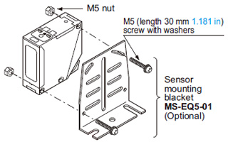
Mounting
|
|
|
|---|
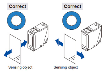
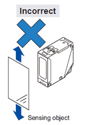 |
| Do not make the sensor detect an object in this direction because it may cause unstable operation. |
|
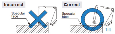
- When detecting a specular object (aluminum or copper foil, etc.) or an object having a glossy surface or coating, please note that there are cases when the object may not be detected due to a change in angle, wrinkles on the object surface, etc.
- If a specular body is present in the background, faulty operation may be caused due to a small change in the angle of the background body. In that case, install the sensor at an inclination and confirm the operation with the actual sensing object.
- When a specular body is present below the sensor, use the sensor by tilting it slightly upwards to avoid faulty operation.
- This product is not easily affected by the reflected light intensity since this sensor is the adjustable range reflective type. When the reflected light intensity is remarkably low, the sensing range may be affected. In that case, mount the sensor, while checking light-up of the stable indicator (green).
- The mounting screws of the terminal cover and VR cover should certainly be tightened to maintain water-resistance; the tightening torque of the screws should be 0.3 to 0.5 N·m.
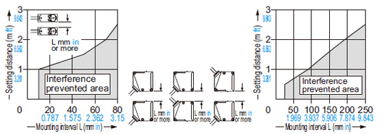
Automatic interference prevention function
- When the sensors are mounted closely, use them in the interference prevented area, as shown below.
|
 |
|
- Note that the detection may be unstable depending on the mounting conditions or the sensing object to be used.
In the state that this product is mounted, be sure to check the operation with the actual sensing object to be used.
Wiring
- Check all wiring before applying power since incorrect wiring may damage the internal circuit. Also, carefully tighten the terminal screws so that the wires of adjacent terminals do not touch.
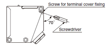
- The mounting hole for the terminal cover fixing screws inclines 70 degrees to the terminal cover, as shown in the figure below.
To avoid damaging this product or screw, take care when tightening or loosening a screw.
- To maintain water-resistance, the cable should have an outer diameter between ø9 to ø11 mm ø0.354 to ø0.433 in with a smooth covering material that allows the attached conduit connector to be securely tightened; the tightening torque of the screw should be of 1.5 to 2.0 N·m.
- If an external surge voltage exceeding 4 kV is impressed (DC-voltage type: 1 kV), the internal circuit will be damaged, and a surge suppressing element should be used.
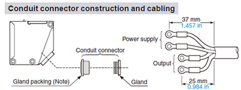
- Prepare the cable end as shown below.
| Note: |
When assembling the conduit connector, pay attention to the direction of the gland packing.
Furthermore, in order to maintain water-resistance, fit the gland packing such that the seating surface of the gland packing contacts the packing holder part of the terminal cover evenly. |
- The size of conduit is M20 × 1.5 mm 0.787 in.
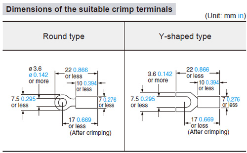
- If pressure terminals are to be used, affix the connected pressure terminals to a terminal (M3.5 screw).
| Note: |
Use crimp terminals with insulating sleeves.
Recommended crimp terminal: Nominal size 1.25 × 3.5 0.049 × 0.138. |
- The tightening torque for the terminal screws should be 0.3 to 0.5 N·m.
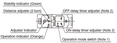
Part description
Notes:
| 1) |
The operation mode switch of the DC-voltage type is the DIP switch.
Refer to ‘DC-voltage type’ of ‘Operation mode switch’ for details. |
| 2) |
Incorporated on EQ-5□T only. |
Operation mode switch
| Multi-voltage type (L-ON / D-ON mode only) |
| Operation mode switch |
Description |
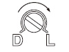 |
Detection-ON mode is obtained when the switch is turned fully clockwise (L side). |
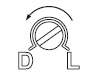 |
Detection-OFF mode is obtained when the switch is turned fully counterclockwise (D side). |
| Note: |
Turn the operation mode switch gradually and lightly with the attached screwdriver. Turning with excessive strength will cause damage to the adjuster. |
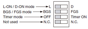
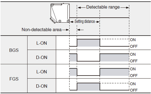
BGS / FGS function (DC-voltage type only)
- DC-voltage type sensor incorporates BGS / FGS function.
Select either the BGS or FGS function depending on the positions of the background and sensing object.
- BGS / FGS function is set with the operation mode switch.
- FGS function is used when the sensing object contacts the background (conveyor, etc).
- Depends on a selection of either BGS or FGS function, the output operation changes as follows.
Timer function (EQ-5□T only)
- EQ-5□ incorporates an OFF-delay timer, which is useful when the response of the connected device is slow, etc., and an ON-delay timer, which is useful for detecting objects that move slowly, for example.
- The OFF-delay and ON-delay timers can be used simultaneously.
- For DC-voltage type, set the DIP switch for the timer mode to ‘Timer ON’ side.
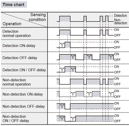 |
| Timer period: T = 0.1 to 5 sec. (variable) |
|
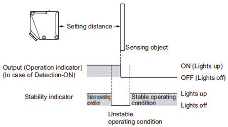
Stability indicator
- Since the EQ-500 series uses a 2-segment photodiode as its receiving element, and sensing is done based on the difference in the incident beam angle of the reflected beam from the sensing object, the output and the operation indicator (orange) operate according to the object distance.
Furthermore, the stability indicator (green) shows the margin of the setting distance.
Others
- Do not use during the initial transient time (50 ms) after the power supply is switched on.
- Its distance adjuster is mechanically operated. Do not drop; avoid other shocks.
Return to top
Return to top

 Business
> Industrial Devices
> Automation Controls Top
> FA Sensors & Components
> Sensors
> Photoelectric Sensors / Laser Sensors
> Adjustable Range Reflective Photoelectric Sensor EQ-500
> Cautions For Use
Business
> Industrial Devices
> Automation Controls Top
> FA Sensors & Components
> Sensors
> Photoelectric Sensors / Laser Sensors
> Adjustable Range Reflective Photoelectric Sensor EQ-500
> Cautions For Use