[System Maintenance Notice]
Due to ongoing system maintenance, the site search and specification search functions are temporarily unavailable. We apologize for any inconvenience this may cause and appreciate your understanding.
【Notification of Manufacturer Change for Panasonic Industrial Devices SUNX Products and Panasonic Industrial Devices SUNX Tatsuno Products】
From April 1, 2024, the terms "Panasonic Industrial Devices SUNX Co., Ltd." and "Panasonic Industrial Devices SUNX Tatsuno Co., Ltd."
in this page and in the manuals and other documents to be downloaded will all be replaced with "Panasonic Industry Co., Ltd." and applied accordingly.

 Business
> Industrial Devices
> Automation Controls Top
> FA Sensors & Components
> Sensors
> Light Curtains / Safety Components
> Ultra-slim Safety Light Curtain Type 4 PLe SIL3 SF4C
> I/O Circuit and Wiring diagrams
Business
> Industrial Devices
> Automation Controls Top
> FA Sensors & Components
> Sensors
> Light Curtains / Safety Components
> Ultra-slim Safety Light Curtain Type 4 PLe SIL3 SF4C
> I/O Circuit and Wiring diagrams
Ultra-slim Safety Light Curtain Type 4 PLe SIL3 SF4C
I/O Circuit and Wiring diagrams
I/O circuit diagram
<In case of using I/O circuit for PNP output>
|
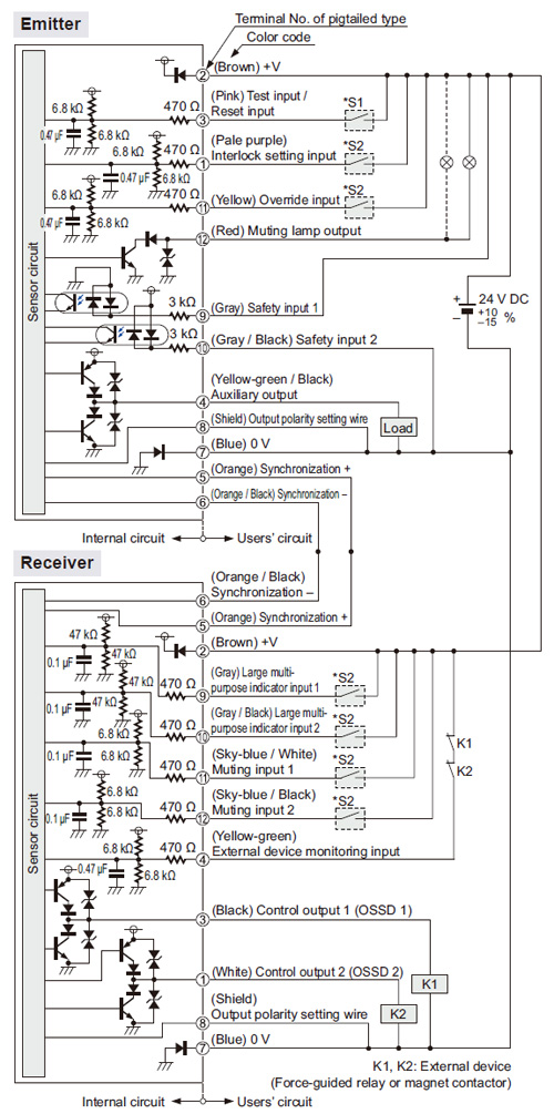
・S1, S2
| Switch S1 | |
| ・ | Test input / Reset input For manual reset Vs to Vs – 3.5 V (sink current 5 mA or less): OFF (Note) Open: ON For automatic reset Vs to Vs – 3.5 V (sink current 5 mA or less): ON (Note) Open: OFF |
|---|---|
| Switch S2 | |
| ・ | Interlock setting input, Override input, Muting input 1 / 2, Large multi-purpose indicator input 1 / 2, Vs to Vs – 3.5 V (sink current 5 mA or less): Valid (Note) Open: Invalid |
| Note: | Vs is the applying supply voltage. |
|---|
<In case of using I/O circuit for NPN output>
|
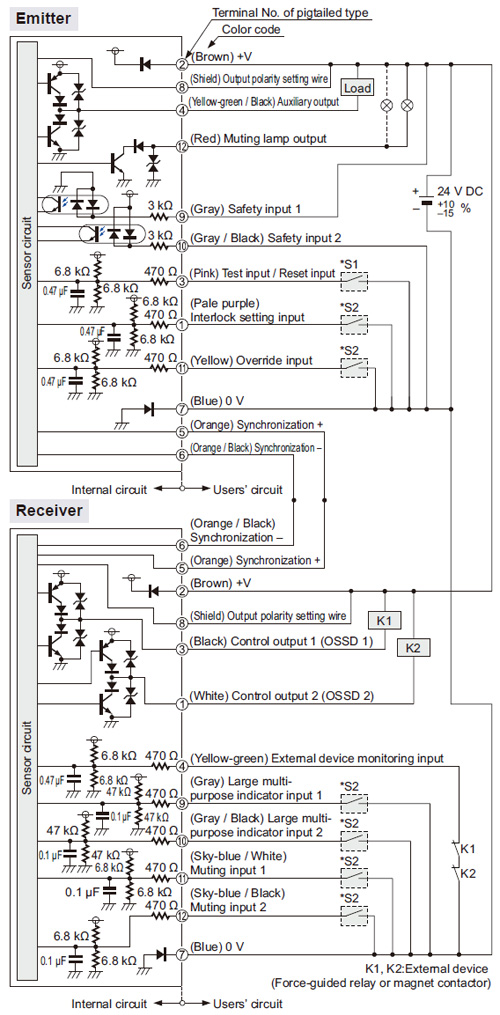
・S1, S2
| Switch S1 | |
| ・ | Test input / Reset input For manual reset 0 to +2.5 V (source current 5 mA or less): OFF Open: ON For automatic reset 0 to +2.5 V (source current 5 mA or less): OFF Open: ON |
|---|---|
| Switch S2 | |
| ・ | Interlock setting input, Override input, Muting input 1 / 2, Large multi-purpose indicator input 1 / 2, 0 to +2.5 V (source current 5 mA or less): Valid Open: Invalid |
Connection example
| Basic wiring: Min. operation only |
This is the general configuration using one set of the emitter and receiver facing each other. The control outputs (OSSD 1 / OSSD 2) turn OFF if the light is interrupted, while they automatically turn ON if receive the light.
The auxiliary output is used to invalid the external device monitoring function. The auxiliary output cannot be connected to external devices.
|
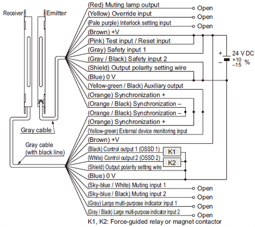
| Interlock function | Disabled (Automatic reset) |
|---|---|
| External device monitoring function | Disabled |
| Auxiliary output | Not used |
| Output polarity setting wire | PNP |
| Safety input | Invalid |
|
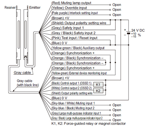
| Interlock function | Disabled (Automatic reset) |
|---|---|
| External device monitoring function | Disabled |
| Auxiliary output | Not used |
| Output polarity setting wire | NPN |
| Safety input | Invalid |
BY EMAIL
- U.S.A.
- +1-800-344-2112
- Europe
- +49-89-45354-1000
- China
- +86-10-59255988
- Singapore
- +65-6299-9181


Requests to customers (Automation Control Components & Industrial Device) [Excluding specific product]
Requests to customers (Automation Control Components & Industrial Device) [For specific product]
Requests to customers (FA Sensors & Components [Excluding motors])
Requests to customers (Dedicated to industrial motors)
- COMPONENTS & DEVICES
- FA SENSORS & COMPONENTS
- Fiber Sensors
- Photoelectric Sensors / Laser Sensors
- Micro Photoelectric Sensors
- Light Curtains / Safety Components
- Area Sensors
- Inductive Proximity Sensors
- Particular Use Sensors
- Sensor Options
- Wire-Saving Systems
- Programmable Controllers / Interface Terminal
- Human Machine Interface
- Pressure Sensors / Flow Sensors
- Measurement Sensors
- Static Control Devices
- Laser Markers / 2D Code Readers
- Machine Vision System
- Energy Management Solutions
- Timers / Counters / FA Components
- MOTORS
![]()