
 Business
> Industrial Devices
> Automation Controls Top
> FA Sensors & Components
> Programmable Controllers / Interface Terminal
> Programmable Controllers / Interface Terminal
> FP0H
> Specifications
Business
> Industrial Devices
> Automation Controls Top
> FA Sensors & Components
> Programmable Controllers / Interface Terminal
> Programmable Controllers / Interface Terminal
> FP0H
> Specifications
FP0H
Specifications
Control units
Control specifications
| Type | Without Ethernet | With Ethernet | |||||
|---|---|---|---|---|---|---|---|
| NPN type | PNP type | NPN type | PNP type | ||||
| Part No. | AFP0HC32T | AFP0HC32P | AFP0HC32ET | AFP0HC32EP | |||
| Number of controllable I/O points | 32 points (Input: 16, Output: 16), When expanded: Max. 384 points | ||||||
| Programming method / Control method |
Relay symbol / Cyclic operation | ||||||
| Program memory | Built-in flash ROM (no backup battery required) | ||||||
| Number of instructions |
Basic instructions | 120 types approx. | |||||
| High-level instructions | 240 types approx. | 270 types approx. | |||||
| Program capacity | 24 k /32 k steps | 24 k /32 k /40 k / 64 k steps | |||||
| Can be selected at system register No. 0 When the program capacity is changed, the number of words that can be used in the data register (DT) is also changed.
|
|||||||
| Operation speed | Basic instruction (NOT: /) : 10 ns/step approx. (Up to 10 k steps) , 0.18 μs/step approx. (10 k steps and later) Basic instruction (ST) : 40 ns/step approx. (Up to 10 k steps) , 0.65 μs/step approx. (10 k steps and later) High-level instruction (FOMV) : 0.14 μs/step approx. (Up to 10 k steps) , 1.2 μs/step approx. (10 k steps and later) |
||||||
| Base scan time I/O refresh and base time |
Control unit: 40 μs or less approx. and FP0 / FP0R expanshion unit refresh time (Note 1) |
Control unit: 100 μs or less approx. and FP0 / FP0R expanshion unit refresh time (Note 1) |
|||||
| Operation memory |
Relay | External input (X) (Note 2, 3) | 1, 760 points (X0 to X109F) | ||||
| External output (Y) (Note 2, 3) | 1, 760 points (Y0 to Y109F) | ||||||
| Internal relay (R) (Note 3) | 4,096 points (R0 to R255F) or 8,192 points (R0 to R511F) (Note 4) |
8,192 points (R0 to R511F) | |||||
| Special internal relay (R) | 800 points (R9000 to R951F) | ||||||
| Timer / Counter (T / C) (Note 5) | 1,024 points (initial setting, timer: 1,008 points, counter: 16 points) | ||||||
| Link relay (L) | 2,048 points (L0 to L127F) | ||||||
| Memory area |
Data register (DT) (Note 6) | 32,765 words or 65,533 words |
12,285 words or 24,573 words or 32,765 words or 65,533 words |
||||
| Special data register (DT) (Note 3) | 1,000 words (DT90000 to DT90999) | ||||||
| Link data register (LD) | 256 words (LD0 to LD255) | ||||||
| Index register (I) | 14 words (I0 to ID) | ||||||
| Differential points | Points for the program capacity | ||||||
| Number of master control relay (MCR) | 256 points | ||||||
| Number of labels (JP and LOOP) | 256 points | ||||||
| Number of step ladder | 1,000 stages | ||||||
| Number of subroutines | 500 subroutines | ||||||
| Number of interrupt program |
9 programs •Input: 8 programs (INT0 to INT7) •Periodic: 1 program (INT24) |
||||||
| Sampling trace (Note 7) | Available [Sampling by commands / Sampling at regular time intervals (For one sampling: 16 bits + 3 words), 1,000 samples] |
||||||
| Comment storage | I/O comments, remarks and block comments can be stored. (no backup battery required, 1 M byte) |
||||||
| PLC link function (Serial communication) |
Max. 16 units, link relays: 1,024 points, link registers: 128 words. (Data transfer and remote programming are not supported) |
||||||
| Constant scan | Available (0 to 600 ms) | ||||||
| Password | Available (32 digits) | ||||||
| Program upload protection | Available | ||||||
| Program protect function | Available | ||||||
| Self-diagnostic function | Watchdog timer, program syntax check, etc. | ||||||
| Program edition during RUN | Available | ||||||
| SD memory card function | - | SD memory card project copy, Logging trace function (Note 7), SD memory card access instruction |
|||||
| Memory transfer | Available [Built-in memory (ROM ⇔ RAM)] | ||||||
| High speed counter (Note 8) |
Main unit input |
Single-phase 4 channels (Max. 100 kHz each input) or 2-phase 2 channels (Max. 50 kHz each input) |
|||||
| Pulse output (Note 8) |
Main unit output |
4 channels (Max. 100 kHz each axis) | |||||
| PWM output (Note 8) |
Main unit output |
4 channels (1 Hz to 70 kHz: 1,000 resolution / 70.001 kHz to 100 kHz: 100 resolution |
|||||
| Pulse catch input Interrupt input |
Total 8 points (with high speed counter) | ||||||
| Periodical interrupt | 0.1 ms to 30 sec. | ||||||
| Potentiometer (Volume) input | 2 channels (0 to 4000) | Not available | |||||
| Clock / calendar (Note 9, 10) | Year (last two digits), month, day, hour (24-hour display), minute, second and day of week | ||||||
| Memory backup (Note 11) |
Backup by instruction P13 |
Data register: all area | |||||
| Auto-backup at power failure |
Counter: 16 points Internal relay: 128 points Data register: 315 words |
||||||
| Battery backup (only when a battery is installed) |
Hold areas or non-hold areas can be specified by setting the system registers No.6 to No. 13. (It is also possible to make the setting for hold all points.) |
||||||
| Battery life | 5 years or more under a production condition (operates for 8 hours per day) | ||||||
Note:
| 1) | Refresh times for FP0 / FP0R expansion units 8 points unit : Number of units×0.8ms 16 points unit : Number of units×1.0ms 32 points unit : Number of units×1.3ms 64 points unit : Number of units×1.9ms |
|---|---|
| 2) | The number of points that can be used depends on the combination of hardware. |
| 3) | Some specifications are compatible with FPΣ. |
| 4) | System register No. 1 (internal relay capacity) can be configured to select "0: 4,096 points / 1: 8,192 points". |
| 5) | An auxiliary timer instruction (F137) can be used to add the number of points. |
| 6) | System register No. 0 (program capacity) can be configured to select the capacity of the data register (DT). |
| 7) | Logging trace and sampling trace cannot be used at the same time. |
| 8) | The specifications are based on the rated input voltage of 24 V DC at +25 ℃ +77 ℉. The maximum operation frequency may be lower depending on the applied voltage, ambient temperature, and conditions of use. The maximum operation frequency varies depending on how the unit is used. |
| 9) | Accuracy of the clock / calendar (within ± 90 seconds per month at +25 ℃ +77 ℉). If an error of the clock / calendar becomes a problem in the system, set an accurate time periodically. |
| 10) | If the battery is not attached, calendar information is cleared when the power is turned off. It will be necessary to set the date when the power is turned on. |
| 11) | Data can be rewritten up to 10,000 times. Hold / non-hold areas can be specified in the system registers. |
General specifications
| Type | Without Ethernet | With Ethernet | ||
|---|---|---|---|---|
| NPN type | PNP type | NPN type | PNP type | |
| Part No. | AFP0HC32T | AFP0HC32P | AFP0HC32ET | AFP0HC32EP |
| CE marking directive compliance | EMC Directive, RoHS Directive | |||
| Rated voltage | 24 V DC | |||
| Operating voltage range | 20.4 to 28.8 V DC | |||
| Consumption current | 140 mA or less | 170 mA or less | ||
| Allowed momentary power off time | 4 ms (at 20.4 V DC), 10 ms (24 V DC or higher) | |||
| Ambient temperature | 0 to +55 ℃ +32 to +131 ℉, At storage: -40 to +70 ℃ - 40 to +158 ℉ | |||
| Ambient humidity | 10 to 95 % RH (at +25 ℃ +77 ℉, no dew condensation allowed), At storage: 10 to 95 % RH (at +25 ℃ +77 ℉, no dew condensation allowed) | |||
| Breakdown voltage (Detection current: 5 mA) |
500 V AC for 1 minute Input and output terminals ⇔ power and functional ground terminals Input terminals ⇔ Output terminals |
|||
| Insulation resistance (Test voltage: 500 V DC) |
100 MΩ or more Input and output terminals ⇔ power and functional ground terminals Input terminals ⇔ Output terminals |
|||
| Vibration resistance | 5 to 8.4 Hz, single amplitude of 3.5 mm 0.138 in, 8.4 to 150 Hz, constant acceleration of 9.8 m/s2, for 10 times each in X, Y, and Z directions (1 octave/min.) (JIS B 3502, IEC 61131-2) | |||
| Shock resistance | 147 m/s2, 4 times each in X, Y, and Z directions (JIS B 3502, IEC 61131-2) | |||
| Noise immunity | 1,000 V (p-p) with pulse widths 50 ns and 1 μs (using a noise simulator) (Power supply terminal) | |||
| Operating condition | Free from corrosive gasses and excessive dust | |||
| Overvoltage category | Category II | |||
| Degree of pollution | Pollution level 2 | |||
| Net weight | 110 g approx. each | 130 g approx. each | ||
COM0 port communication specifications
| Item | Specifications | |
|---|---|---|
| Interface | RS-232C, three-wire system, 1 channel (Not insulated) | |
| Transmission distance | 15 m 49.213 ft | |
| Communication configuration | 1 : 1 communication | |
| Communication method | Half-duplex system | |
| Synchronous method | Start-stop synchronization system | |
| Transmission cable | Multi-conductor shielded wire | |
| Communication speed (Specified at the system registers) |
1,200(Note 3), 2,400(Note 3), 4,800, 9,600, 19,200, 38,400, 57,600, 115,200, 230,400 bits/sec. | |
| Transmission format |
Data length | 7 bits / 8 bits |
| Parity | none / odd / even | |
| Stop bit | 1 bit / 2 bits | |
| Start code | with STX / without STX | |
| End code | CR / CR + LF / none / ETX / Time (0 to 100.00 ms) | |
| Data transmission order | Transmit from bit 0 in character units | |
| Communication mode | MEWTOCOL-COM (Master / Slave) (Computer link) General-purpose communication PLC link MODBUS RTU (Master / Slave) |
|
Notes:
| 1) | The start and end codes can be used only for general-purpose serial communications. |
|---|---|
| 2) | The unit No. (station number) can be selected at system register No. 410. |
| 3) | System register no. 415 cannot be used to set the baud rate to 1,200 bps. To set the baud rate to 1,200 bps, use the SYS1 instruction. If the baud rate of any of the COM ports is 2,400 bps or lower, F-ROM access will slow down. Example) F12(ICRD) instruction, P13(ICWT) instruction, etc. |
LAN port communication specifications (for only Ethernet type)
| Item | Specifications |
|---|---|
| Communication interface | Ethernet 100BASE-TX / 10BASE-T |
| Baud rate | 100 Mbps, 10 Mbps auto negotiation function |
| Total cable length | 100 m 328.084 ft (500 m 1640.420 ft when a repeater is used) |
| Number of simultaneous connections | Max. 10 (system connection: 1, user connection: 9) |
| Communication method | Full duplex / Half-duplex system |
| Communication protocol (Communication layer) |
TCP / IP, UDP |
| DNS | Supports name servers |
| DHCP | Automatic IP address acquisition |
| FTP server / Client | File transmission, server function, No. of users:1 Client function, Data file transfer |
| SNTP | Time adjustment function |
| General-purpose communication | 4 kB / 1 connection (user connection: 1 to 9) (Note 2) |
| Dedicated communication | EtherNet/IP MEWTOCOL-COM (Master / Slave) (Computer link) MODBUS-TCP (Master / Slave) MEWTOCOL-DAT (Master / Slave) General-purpose communication MC protocol (Note 1) (Master / Slave) |
Notes:
| 1) | MC protocol is a short form denoting MELSEC communication protocol; MELSEC is a registered trademark of Mitsubishi Electric Corporation. QnA compatible 3E frame, only binary (bulk writing and bulk reading) use is available. |
|---|---|
| 2) | General-purpose communications can be up to 4 kB (reception) and up to 2 kB (transmission) per connection. |
USB port specifications
| Item | Specifications |
|---|---|
| Standard | USB2.0 Full speed (USB mini B type) |
| Communication function | Computer link (slave) |
Dedicated power supply output port specifications for GT series programmable display
| Output terminal | Connecting programmable display model |
|---|---|
| 5 V DC | For 5 V DC type GT02 series Programmable Display |
Input specifications
| Item | Specifications | |
|---|---|---|
| Rated input voltage | 24 V DC | |
| Operating voltage range | 21.6 to 26.4 V DC | |
| Rated input current | High-speed part (X0 to X7) : 8 mA approx. Low-speed part (X8 to XF) : 3.5 mA approx. |
|
| Input points per common | 16 points/common (Either the positive or negative of the input power supply can be connected to the common terminal.) |
|
| Min. ON voltage / Min. ON current | High-speed part (X0 to X7) : 19.2 V DC / 6 mA Low-speed part (X8 to XF) : 19.2 V DC / 3 mA |
|
| Max. OFF voltage / Max. OFF current | 2.4 V DC / 1 mA | |
| Input impedance | High-speed part (X0 to X7) : 3 kΩ approx. Low-speed part (X8 to XF) : 6.8 kΩ approx. |
|
| Response time (Note) |
OFF → ON | <High-speed part (X0 to X7)> 135 μs or less: normal input 5 μs or less: high speed counter, pulse catch, interrupt input settings <Low-speed part (X8 to XF)> 1 ms or less: normal input only |
| ON → OFF | Same as above | |
| Operating mode indicator | LED display | |
Note: The input time constant (0.1 to 256 ms) can be specified.
Output specifications
| Type | Without Ethernet |
With Ethernet |
Without Ethernet |
With Ethernet |
|
|---|---|---|---|---|---|
| Part No. | AFP0HC32T | AFP0HC32ET | AFP0HC32P | AFP0HC32EP | |
| Output type | Nch open drain | Pch open drain | |||
| Rated load voltage | 5 to 24 V DC | 24 V DC | |||
| Operating load voltage range | 4.75 to 26.4 V DC | 21.6 to 26.4 V DC | |||
| Rated load current | 0.3 A (For Y0, Y1, Y3, Y4, Y8,Y9, YB,YC), 0.1 A (For Y2, Y5, Y6, Y7, YA, YD, YE, YF) |
0.3 A (For Y0 to YF) | |||
| Max. surge current | High-speed part (For Y0, Y1, Y3, Y4, Y8, Y9, YB, YC) : 1.0 A, Low-speed part (For Y2, Y5, Y6, Y7, YA, YD, YE, YF) : 0.5 A |
||||
| OFF state leakage current | 110 μA or less | 20 μA or less | |||
| ON state voltage drop | 0.5 V DC or less | ||||
| Overcurrent protection | Provided (automatically protected for each 8 points) | ||||
| Output points per common | 16 points/common (Y0 to YF / 1 common) | ||||
| Response time |
OFF → ON | High-speed part (For Y0, Y1, Y3, Y4, Y8, Y9, YB, YC) : 2 μs or less, Low-speed part (For Y2, Y5, Y6, Y7, YA, YD, YE, YF) : 1 ms or less |
|||
| ON → OFF | High-speed part (For Y0, Y1, Y3, Y4, Y8, Y9, YB, YC) : 5 μs or less, Low-speed part (For Y2, Y5, Y6, Y7, YA, YD, YE, YF) : 1 ms or less |
||||
| Surge absorber | Zener diode | ||||
| Operating mode indicator | LED display | ||||
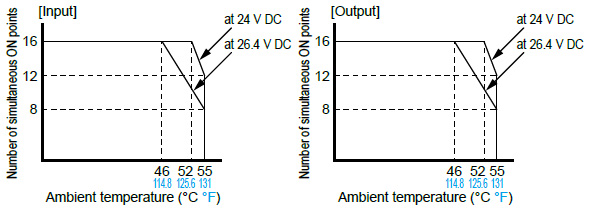
Limitations on simultaneous ON points
|
Current consumption
| Type of unit | Control unit current consumption (at 24 V DC) |
Additional current (at 24 V DC) |
Expansion unit current consumption (at 24 V DC) |
|
|---|---|---|---|---|
| Control unit alone |
AFP0HC32T | 140 mA or less | - | - |
| AFP0HC32P | ||||
| AFP0HC32ET | 170 mA or less | |||
| AFP0HC32EP | ||||
| Extension unit attached |
AFP0HXY64D2T | - | 35 mA or less | - |
| AFP0HXY64D2P | ||||
| AFP0HPG01T | 50 mA or less | 20 mA or less | ||
| AFP0HPG01L | ||||
| AFP0HPG02T | 70 mA or less | 35 mA or less | ||
| AFP0HPG02L | ||||
| AFP0HM4N | 90 mA or less | - | ||
| AFP0HM8N | ||||
| Extension cassette attached |
AFP0HCCS1 | - | 10 mA or less | - |
| AFP0HCCS2 | ||||
| AFP0HCCM1 | 30 mA or less | |||
| AFP0HCCS1M1 | ||||
| Note: | For details about the current consumption of FPΣ expansion units and FP0 / FP0R expansion units, refer to relevant specifications and manuals. |
|---|
Expansion I/O unit
General specifications
| Item | Specifications |
|---|---|
| Ambient temperature | 0 to +55 ℃ +32 to +131 ℉, At storage: -20 to +70 ℃ - 4 to +158 ℉ |
| Ambient humidity | 30 to 85 % RH (at +25 ℃ +77 ℉, no dew condensation allowed), At storage: 30 to 85 % RH (at +25 ℃ +77 ℉, no dew condensation allowed) |
| Breakdown voltage (Detection current: 5 mA) |
500 V AC for 1 minute Input and output terminals ⇔ power and functional ground terminals (at control unit) Input terminals ⇔ Output terminals |
| Insulation resistance (Test voltage: 500 V DC) |
100 MΩ or more Input and output terminals ⇔ power and functional ground terminals (at control unit) Input terminals ⇔ Output terminals |
| Vibration resistance | 10 to 55 Hz, 1 sweep/min., double amplitude of 0.75 mm 0.030 in, 10 minutes each in X, Y, and Z directions |
| Shock resistance | 98 m/s2, 4 times each in X, Y, and Z directions |
| Noise immunity | 1,000 V (p-p) with pulse widths 50 ns and 1 μs (using a noise simulator) |
| Operating condition | Free from corrosive gasses and excessive dust |
| Net weight | 100 g approx. |
| Control unit's additional consumption current |
35 mA or less (at 24 V DC) [100 mA or less (internal 5 V DC)] |
Input specifications
| Item | Specifications | |
|---|---|---|
| Insulation method | Photocoupler | |
| Rated input voltage | 24 V DC | |
| Operating voltage range | 21.6 to 26.4 V DC | |
| Rated input current | 3.5 mA approx. | |
| Input points per common | 32 points/common (Either the positive or negative of the input power supply can be connected to the common terminal.) |
|
| Min. ON voltage / Min. ON current | 19.2 V DC / 3 mA | |
| Max. OFF voltage / Max. OFF current | 2.4 V DC / 1.3 mA | |
| Input impedance | 6.8 kΩ approx. | |
| Response time |
OFF→ON | 0.2 ms or less |
| ON→OFF | 0.3 ms or less | |
| Operating mode indicator | LED display | |
Output specifications
| Type | Sink | Source | |
|---|---|---|---|
| Part No. | AFP0HXY64D2T | AFP0HXY64D2P | |
| Insulation method | Photocoupler | ||
| Output type | Open collector (NPN) | Open collector (PNP) | |
| Rated load voltage | 5 to 24 V DC | 24 V DC | |
| Operating load voltage range | 4.75 to 26.4 V DC | 21.6 to 26.4 V DC | |
| Rated load current | 0.1 A | ||
| Max. surge current | 0.5 A | ||
| Output points per common | 32 points/common | ||
| OFF state leakage current | 100 μA or less | ||
| ON state voltage drop | 0.5 V DC or less | ||
| Response time | OFF → ON | 0.2 ms or less | |
| ON → OFF | 0.5 ms or less | ||
| External power supply (for driving internal circuit) |
Voltage | 21.6 to 26.4 V DC | |
| Current | 35 mA or less | 40 mA or less | |
| Surge absorber | Zener diode | ||
| Operating mode indicator | LED display | ||
| Short circuit protection | Short circuit protection, Thermal protection | ||
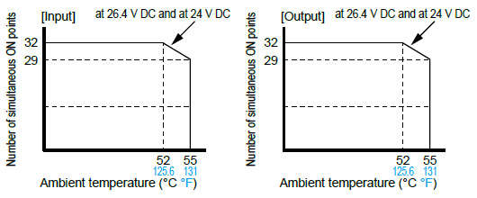
Number of simultaneous ON points
|
Communication cassettes
Specifications
| Item | Specifications | |||||
|---|---|---|---|---|---|---|
| AFP0HCCS1 | AFP0HCCS2 | AFP0HCCM1 | AFP0HCCS1M1 | |||
| Interface | RS-232C 1 channel | RS-232C 2 channels | RS-485 1 channel | RS-232C 1 channel and RS-485 1 channel |
||
| Transmission distance | Max. 15 m 49.213 ft | Max. 1,200 m 3,937.008 ft |
RS-232C Max. 15 m 49.213 ft |
RS-485 Max. 1,200 m 3,937.008 ft |
||
| Communication configuration | 1 : 1 communication | 1 : N communication | 1 : 1 communication | 1 : N communication | ||
| Communication speed | 1,200(Note 1), 2,400(Note 1), 4,800, 9,600, 19,200, 38,400, 57,600, 115,200, 230,400 bits/sec. | |||||
| Communication method | Half-duplex system | |||||
| Synchronous method | Start-stop synchronization system | |||||
| Transmission format |
Data length | 7 bits / 8 bits | ||||
| Parity | none / odd / even | |||||
| Stop bit | 1 bit / 2 bits | |||||
| Start code | with STX / without STX | |||||
| End code | CR / CR + LF / none / ETX / Time (0 to 100 ms) | |||||
| Data transmission order | Transmit from bit 0 in character units. | |||||
| Number of stations | - | - | Max. 99 units | - | Max. 99 units | |
| Net weight | 10 g approx. each | |||||
Notes:
| 1) | System register no. 415 cannot be used to set the baud rate to 1,200 bps. To set the baud rate to 1,200 bps, use the SYS1 instruction. If the baud rate of any of the COM ports is 2,400 bps or lower, F-ROM access will slow down. Example) F12(ICRD) instruction, P13(ICWT) instruction, etc. |
|---|---|
| 2) | The start and end codes can be used only for general-purpose serial communications. |
| 3) | The unit No. (station number) can be selected at system register. |
| 4) | Sufficient noise tolerance is provided but it is recommended that a user program be created for retransmission. (To improve the reliability of communications when a communication error occurs due to an excessive noise or when the target device cannot receive data temporarily.) |
| 5) | When connecting a commercially available device that has an RS-485 interface, please confirm operation using the actual device. In some cases, the number of station units, transmission distance and communication speed vary depending on the connected device. |
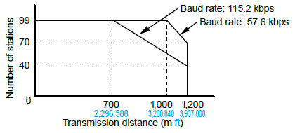
| 6) | The transmission distance, transmission speed, and number of stations should be within the range of the graph below, depending on each value. |
|
Positioning units
Specifications
| Part No. | AFP0HPG01T | AFP0HPG01L | AFP0HPG02T | AFP0HPG02L | |
|---|---|---|---|---|---|
| Output type | Transistor | Line driver | Transistor | Line driver | |
| Number of occupied points | Input 16 points, Output 16 points | Input 32 points, Output 32 points | |||
| Number of axes controlled | 1 axis | 2 axes, independent | |||
| Position command |
Command units | Pulse unit (The program specifies whether Increment or Absolute is used.) | |||
| Max. pulse count | Signed 32 bits (-2,147,483,648 to +2,147,483,647 pulses) | ||||
| Speed command |
Command range |
1 pps to 500 kpps (can set in 1 pps.) |
1 pps to 4 Mpps (can set in 1 pps.) |
1 pps to 500 kpps (can set in 1 pps.) |
1 pps to 4 Mpps (can set in 1 pps.) |
| Acceleration / deceleration command |
Acceleration / deceleration method |
Linear acceleration / deceleration, S acceleration / deceleration | |||
| S-curve type | Can select from Sin curve, Secondary curve, Cycloid curve and Third curve. | ||||
| Acceleration / deceleration time |
0 to 32,767 ms (can set in 1 ms) | ||||
| Home return |
Home return speed | Speed setting possible (changes return speed and search speed) | |||
| Input signal | Home input, Near home input, Over limit input (+), Over limit input (-) | ||||
| Output signal | Deviation counter clear signal | ||||
| Operation mode | E point control (Linear accelerations / decelerations, S accelerations / decelerations) P point control (Linear accelerations / decelerations, S accelerations / decelerations) Home return function (Home search) JOG operation function (Note 1) JOG positioning function Pulser input function (Note 3) • Transfer multiplication ratio (× 1, × 2, × 5, × 10, × 50, × 100, × 500, × 1000) Real-time frequency change function Infinity output function |
||||
| Startup time | 0.02 ms or 0.005 ms selectable (Note 2) | ||||
| Output interface | Output mode | 1 pulse output (Pulse and Sign), 2-pulse output (CW and CCW) | |||
| Feed back counter function (Note 3) |
Countable range | Signed 32 bits (-2,147,483,648 to +2,147,483,647 pulses) | |||
| Input mode | Two-phase input, Direction distinction input, Individual input (transfer multiple available for each.) | ||||
| Other functions | The flag to compare the elapsed value is built in. (The timing signal outputs at the optional position during an operation.) | ||||
| External power supply |
Voltage | 21.6 to 26.4 V DC | |||
| Current consumption | 20 mA | 30 mA | |||
| Net weight | 75 g approx. each | 80 g approx. each | |||
Notes:
| 1) | When selected linear acceleration / deceleration operation, the target speed can be changed during an operation. |
|---|---|
| 2) | The startup time can be changed by the control code setting in the shared memory. The factory setting (default setting) is 0.02 ms. The startup time is the time from the start request to the first pulse output. |
| 3) | Pulser input function and feedback counter function use the same pulse input terminal, so the both cannot function simultaneously. |
Positioning RTEX units
Specifications
| Type | 4-axis type | 8-axis type | Part No. | AFP0HM4N | AFP0HM8N | |
|---|---|---|---|---|---|---|
| Number of axes controlled | 4 axes | 8 axes | ||||
| Interpolation control | 2-axis linear interpolation, 2-axis circular interpolation, 3-axis linear interpolation and 3-axis spiral interpolation |
|||||
| Occupied I/O points | 128 input points, 128 output points | |||||
| Automatic operation |
Position control |
Position specification mode | Absolute (Absolute position specifi cation), Increment (Relative position specifi cation) | |||
| Position specified unit | pulse μm (Min. unit of instruction selectable between 0.1 μm and 1 μm) inch (Min. unit of instruction selectable between 0.00001 inch and 0.0001 inch) degree (Min. unit of instruction selectable between 0.1 degree and 1 degree) |
|||||
| Position setting range | pulse : -2,147,482,624 to 2,147,482,624 pulse μm (0.1 μm) : -214,748,262.4 to 214,748,262.4 μm μm (1 μm) : -2,147,482,624 to 2,147,482,624 μm inch (0.00001 inch) : -21,474.82624 to 21,474.82624 inch inch (0.0001 inch) : -214,748.2624 to 214,748.2624 inch degree (0.1 degree) : -214,748,262.4 to 214,748,262.4 degree degree (1 degree) : -2,147,482,624 to 2,147,482,624 degree |
|||||
| Speed reference range | pulse : 1 to 2,147,482,624 pps μm : 1 to 2,147,482,624 μm/s inch : 0.001 to 2,147,482.624 inch/s degree : 0.001 to 2,147,482.624 rev/s |
|||||
| Acceleration and deceleration method |
Linear acceleration / deceleration, S acceleration / deceleration | |||||
| Acceleration time | 0 to 10,000 ms (Settable by 1 ms) | |||||
| Deceleration time | 0 to 10,000 ms (Settable by 1 ms) | |||||
| No. of positioning tables |
Each axis : 600 points in standard area and 89 points in extended area | |||||
| Control method | Independent | PTP control (E-point control, C-point control), CP control (P-point control), Speed control (J-point control) |
||||
| 2-axis interpolation |
Linear interpolation |
E point, P point, C point controls, Composite speed or Long axis speed | ||||
| Circular interpolation |
E point, P point, C point controls, Center point or Pass point | |||||
| 3-axis interpolation |
Linear interpolation |
E point, P point, C point controls, Composite speed or Long axis speed | ||||
| Spiral interpolation |
E point, P point, C point controls, Center point or Pass point | |||||
| Startup time | Standard area : 3 ms or less, Extended area : 5 ms or less | |||||
| Other functions |
Dwell time |
0 to 32,767 ms (Settable by 1 ms) | ||||
| Manual operation |
JOG operation | Speed reference range | pulse : 1 to 2,147,482,624 pps μm : 1 to 2,147,482,624 μm/s inch : 0.001 to 2,147,482.624 inch/s degree : 0.001 to 2,147,482.624 rev/s |
|||
| Acceleration / deceleration method |
Linear acceleration / deceleration, S acceleration / deceleration | |||||
| Acceleration time | 0 to 10,000 ms (Settable by 1 ms) | |||||
| Deceleration time | 0 to 10,000 ms (Settable by 1 ms) | |||||
| Home return (Note) |
Speed reference range | pulse : 1 to 2,147,482,624 pps μm : 1 to 2,147,482,624 μm/s inch : 0.001 to 2,147,482.624 inch/s degree : 0.001 to 2,147,482.624 rev/s |
||||
| Acceleration / deceleration method |
Linear acceleration/deceleration | |||||
| Acceleration time | 0 to 10,000 ms (Settable by 1 ms) | |||||
| Deceleration time | 0 to 10,000 ms (Settable by 1 ms) | |||||
| Return method | DOG method (3 types), Limit method (2 types), Data set method, Z phase method, Stop-on-contact method (2 types) |
|||||
| Pulsar operation |
Speed reference range | Operation synchronized with inputs from pulser | ||||
| Stop function |
Deceleration stop | Deceleration time | Deceleration time of the operation being active | |||
| Emergency stop | Deceleration time | 0 to 10,000 ms (Settable by 1 ms) | ||||
| Limit stop | Deceleration time | 0 to 10,000 ms (Settable by 1 ms) | ||||
| Error stop | Deceleration time | 0 to 10,000 ms (Settable by 1 ms) | ||||
| System stop | Deceleration time | Immediate stop (0 ms) | ||||
| Synchronous functions |
Supported functions | Electronic gear, Electronic clutch, Electronic cam | ||||
| No. of axes | No. of synchronous groups |
4 groups | ||||
| Master axis | Selectable from real axes, virtual axes and pulse inputs. | |||||
| Slave axis | Max. 8 axes per master axis | |||||
| Electronic gear | Operation setting | Gear ratio setting | ||||
| Operation method | Direct method, Linear acceleration / deceleration method | |||||
| Electronic clutch | Trigger type | Clutch ON trigger : Contact method Clutch OFF trigger : Contact input, The contact input + phase specifi cation Contact method can be selected from the edge and level types. |
||||
| Connection method | Direct method, Linear slide method | |||||
| Electronic cam | Cam curve | Select from 20 types. Multiple curves can be specifi ed within phase (0 to 100 %) | ||||
| Resolution | 1,024, 2,048, 4,096, 8,192, 16,384, 32,768 | |||||
| No. of cam patterns |
4 to 16 (According to resolution) | |||||
| Cam pattern configuration method |
Cam curve method, Cam point method (set from Confi gurator PM7-RTEX) | |||||
| Other specifications | Software limit function |
Setting range | pulse : -2,147,482,624 to 2,147,482,624 pulse μm (0.1 μm) : -214,748,262.4 to 214,748,262.4 μm μm (1 μm) : -2,147,482,624 to 2,147,482,624 μm inch (0.00001 inch) : -21,474.82624 to 21,474.82624 inch inch (0.0001 inch) : -214,748.2624 to 214,748.2624 inch degree (0.1 degree) : -214,748,262.4 to 214,748,262.4 degree degree (1 degree) : -2,147,482,624 to 2,147,482,624 degree |
|||
| Monitor judgement |
Torque judgement | Torque judgement : Selectable from Enabled / Disabled, Error / Warning 0.0 to 500.0 % |
||||
| Actual speed judgement |
Actual speed judgement : Selectable from Enabled / Disabled, Error / Warning 0 to 5,000 rpm |
|||||
| Backup | Parameters and positioning data are saved in the fl ash memory. (Battery less) | |||||
| ・ Limit input CWL, CCWL monitor, Proximity (DOG) monitor ・ General-purpose input : 2 points, General-purpose output : 2 points (input and output from driver) ・ Auxiliary output contact, Auxiliary output code ・ Torque limit function |
||||||
| (Note) : | "Servo motor with an absolute encoder" supported Absolute home return is performed in combination with A6-family servo motor with an absolute encoder. For servo drivers of A6NF and A6NE. Servo drivers with software of Ver. 1.24 (A6NF and A6NE) or later supported |
|---|
Related Information
CONTACT US
If you have any questions, please select the option below to contact us or find answers.
CONTACT US
BY EMAIL
BY EMAIL
Please click your area to select country or region


Related Information
Service & Support
Requests to customers (Automation Control Components & Industrial Device) [Excluding specific product]
Requests to customers (Automation Control Components & Industrial Device) [For specific product]
Requests to customers (FA Sensors & Components [Excluding motors])
Requests to customers (Dedicated to industrial motors)
- COMPONENTS & DEVICES
- FA SENSORS & COMPONENTS
- Fiber Sensors
- Photoelectric Sensors / Laser Sensors
- Micro Photoelectric Sensors
- Light Curtains / Safety Components
- Area Sensors
- Inductive Proximity Sensors
- Particular Use Sensors
- Sensor Options
- Wire-Saving Systems
- Programmable Controllers / Interface Terminal
- Human Machine Interface
- Pressure Sensors / Flow Sensors
- Measurement Sensors
- Static Control Devices
- Laser Markers / 2D Code Readers
- Machine Vision System
- Energy Management Solutions
- Timers / Counters / FA Components
- MOTORS
![]()