[System Maintenance Notice]
Due to ongoing system maintenance, the site search and specification search functions are temporarily unavailable. We apologize for any inconvenience this may cause and appreciate your understanding.
【Notification of Manufacturer Change for Panasonic Industrial Devices SUNX Products and Panasonic Industrial Devices SUNX Tatsuno Products】
From April 1, 2024, the terms "Panasonic Industrial Devices SUNX Co., Ltd." and "Panasonic Industrial Devices SUNX Tatsuno Co., Ltd."
in this page and in the manuals and other documents to be downloaded will all be replaced with "Panasonic Industry Co., Ltd." and applied accordingly.
Compact Size Picking Sensor NA1-PK3
Cautions For Use
- Never use this product as a sensing device for personnel protection.
- For sensing devices to be used as safety devices for press machines or for personnel protection, use products which meet standards, such as OSHA, ANSI or IEC etc., for personnel protection applicable in each region or country.
- If this product is used as a sensing device for personnel protection, death or serious body injury could result.
- For a product which meets safety standards,
use the safety light curtain.
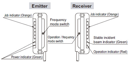
Part description
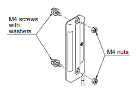
Mounting
- Use M4 screws with washers and M4 nuts. The tightening torque should be 0.5 N·m or less.
(Purchase the screws and nuts separately.)
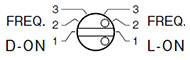
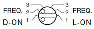
Selection of operation
- The output operation can be selected by the operation / frequency selection switch on the receiver.
(Make sure that the power supply is off while setting the selection switch.)
| |
State of operation / frequency selection switch |
Output operation |
| L-ON |
 |
OFF when one or more beams are interrupted. |
| D-ON |
 |
ON when one or more beams are interrupted. |
Notes:
| 1) |
Selection of the output operation and the frequency for the receiver is carried out with the same switch. When the output operation is set, be sure to select the same frequency No. of the emitter and the receiver. |
| 2) |
In case the operation / frequency selection switch is set to the position other than 1, 2 or 3, the state of the receiver is in D-ON / frequency 1. |
Orientation
- The emitter and the receiver must face each other correctly.
If they are set upside down, the sensor does not work.
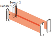
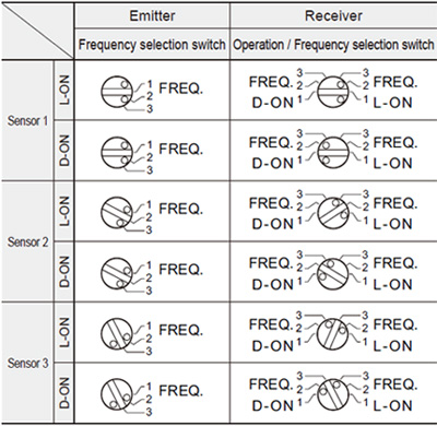
Interference prevention function
- By setting different emission frequencies, three units of NA1-PK3 can be mounted close together, as shown in the figure on the below.
- However, if the sensors are mounted close together as shown in the figure below, up to 2 sets of sensors are possible.
- Set the both emitting and receiving frequency of Sensor 1 to FREQ. 1, the both emitting and receiving frequency of Sensor 2 to FREQ. 2 and the both emitting and receiving frequency of Sensor 3 to FREQ. 3.
(Make sure that the power supply is off while setting the selection switch.)
Notes:
| 1) |
Take care that selection of the output operation and the frequency for the receiver is carried out with the same switch. |
| 2) |
In case the frequency switch and the operation / frequency selection switch is set to the position other than 1, 2 or 3, the state of the emitter is in frequency 1 and that of the receiver is in D-ON / frequency 1. |
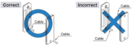
Wiring
- Make sure that the power supply is off while wiring and setting the selection switch.
- Take care that wrong wiring may damage the sensor.
- Verify that the supply voltage variation is within the rating.
- If power is supplied from a commercial switching regulator, ensure that the frame ground (F.G.) terminal of the power supply is connected to an actual ground.
- In case noise generating equipment (switching regulator, inverter motor, etc.) is used in the vicinity of the sensor, connect the frame ground (F.G.) terminal of the equipment to an actual ground.
- Extension up to total 100 m 328.084 ft is possible with 0.3 mm2, or more, cable for both emitter and receiver.
However, in order to reduce noise, make the wiring as short as possible.
- Do not run the wires together with high-voltage lines or power lines or put them in the same raceway. This can cause malfunction due to induction.
- Make sure to use an isolation transformer for the DC power supply. If an auto-transformer (single winding transformer) is used, this product or the power supply may get damaged.
- In case a surge is generated in the used power supply, connect a surge absorber to the supply and absorb the surge.
Others
- Do not use during the initial transient time (0.5 sec.) after the power supply is switched on.
- Take care that the sensor is not directly exposed to fluorescent light from a rapid-starter lamp or a high frequency lighting device, as it may affect the sensing performance.
- Avoid dust, dirt, and steam.
- Take care that the product does not come in direct contact with water, oil, grease or organic solvents, such as, thinner, etc.
- To select the switch, a minus screwdriver is necessary.
(Tip dimension: 2.5 × 0.6 mm 0.098 × 0.024 in)
- These sensors are only for indoor use.
Return to top
Return to top

 Business
> Industrial Devices
> Automation Controls Top
> FA Sensors & Components
> Sensors
> Area Sensors
> Compact Size Picking Sensor NA1-PK3
> Cautions For Use
Business
> Industrial Devices
> Automation Controls Top
> FA Sensors & Components
> Sensors
> Area Sensors
> Compact Size Picking Sensor NA1-PK3
> Cautions For Use