[System Maintenance Notice]
Due to ongoing system maintenance, the site search and specification search functions are temporarily unavailable. We apologize for any inconvenience this may cause and appreciate your understanding.
【Notification of Manufacturer Change for Panasonic Industrial Devices SUNX Products and Panasonic Industrial Devices SUNX Tatsuno Products】
From April 1, 2024, the terms "Panasonic Industrial Devices SUNX Co., Ltd." and "Panasonic Industrial Devices SUNX Tatsuno Co., Ltd."
in this page and in the manuals and other documents to be downloaded will all be replaced with "Panasonic Industry Co., Ltd." and applied accordingly.

 Business
> Industrial Devices
> Automation Controls Top
> FA Sensors & Components
> Sensors
> Area Sensors
> Compact Size Picking Sensor NA1-PK3
> Specifications
Business
> Industrial Devices
> Automation Controls Top
> FA Sensors & Components
> Sensors
> Area Sensors
> Compact Size Picking Sensor NA1-PK3
> Specifications
Compact Size Picking Sensor NA1-PK3
|
Specifications
| Type | NPN output | PNP output | |
|---|---|---|---|
| Model No. | NA1-PK3 | NA1-PK3-PN | |
| Sensing height | 49.2 mm 1.937 in | ||
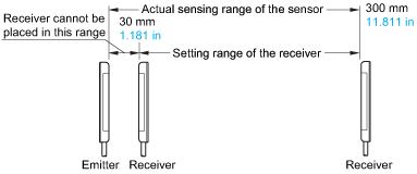
| Sensing range (Note 2) | 30 to 300 mm 1.181 to 11.811 in | ||
| Beam pitch | 24.6 mm 0.969 in | ||
| Number of beam channels | 3 beam channels | ||
| Sensing object | ø29 mm ø1.142 in or more opaque object (completely beam interrupted object) |
||
| Supply voltage | 12 to 24 V DC ± 10 % Ripple P-P 10 % or less | ||
| Current consumption | Emitter: 30 mA or less, Receiver: 50 mA or less | ||
| Output | NPN open-collector transistor ・ Maximum sink current: 100 mA ・ Applied voltage: 30 V DC or less (between output and 0 V) ・ Residual voltage: 1 V or less (at 100 mA sink current) 0.4 V or less (at 16 mA sink current) |
PNP open-collector transistor ・ Maximum source current: 100 mA ・ Applied voltage: 30 V DC or less (between output and +V) ・ Residual voltage: 1 V or less (at 100 mA source current) 0.4 V or less (at 16 mA source current) |
|
| Utilization category | DC-12 or DC-13 | ||
| Output operation | ON or OFF when one or more beam channels are interrupted, selectable by operation mode switch | ||
| Short-circuit protection | Incorporated | ||
| Response time | 10 ms or less (when interference prevention function is used: 30 ms or less) |
||
| Indicators | Emitter | Power indicator: Green LED (lights up when the power is ON) Job indicator: Orange LED (lights up when the job indicator input is Low) |
Power indicator: Green LED (lights up when the power is ON) Job indicator: Orange LED (lights up when the job indicator input is High) |
| Receiver | Operation indicator: Red LED (lights up when the output is ON) Stable incident beam indicator: Green LED (lights up when all beam channels are stably received) Job indicator: Orange LED (lights up when the job indicator input is Low) |
Operation indicator: Red LED (lights up when the output is ON) Stable incident beam indicator: Green LED (lights up when all beam channels are stably received) Job indicator: Orange LED (lights up when the job indicator input is High) |
|
| Interference prevention function | Incorporated (Up to 3 units can be mounted close together.) |
||
| Pollution degree | 3 (Industrial environment) | ||
| Protection | IP62 (IEC) | ||
| Ambient temperature | -10 to +55 ℃ +14 to +131 ℉ (No dew condensation or icing allowed), Storage: -20 to +70 ℃ -4 to +158 ℉ |
||
| Ambient humidity | 35 to 85 % RH, Storage: 35 to 85 % RH | ||
| Ambient illuminance | Incandescent light: 3,000 lx or less at the light-receiving face | ||
| Voltage withstandability | 1,000 V AC for one min. between all supply terminals connected together and enclosure | ||
| Insulation resistance | 20 MΩ, or more, with 250 V DC megger between all supply terminals connected together and enclosure | ||
| Vibration resistance | 10 to 150 Hz frequency, 0.75 mm 0.030 in (5 G max.) double amplitude in X, Y and Z directions for two hours each | ||
| Shock resistance | 500 m/s2 acceleration (50 G approx.) in X, Y and Z directions three times each | ||
| Emitting element | Infrared LED (synchronized scanning system) | ||
| Material | Enclosure: Heat-resistant ABS, Lens cover: Acrylic, Indicator cover: Acrylic | ||
| Cable | 0.2 mm2 4-core (emitter: 3-core) oil resistant cabtyre cable, 2 m 6.562 ft long | ||
| Cable extension | Extension up to total 100 m 328.084 ft is possible for both emitter and receiver with 0.3 mm2 , or more, cable. | ||
| Net weight | Emitter: 50 g approx., Receiver: 50 g approx. | ||
| Note 1 : | Where measurement conditions have not been specified precisely, the conditions used were an ambient temperature of +23 ℃ +73.4 ℉. |
|---|---|
| Note 2 : | The sensing range is the possible setting distance between the emitter and the receiver. |
|
BY EMAIL


Requests to customers (Automation Control Components & Industrial Device) [Excluding specific product]
Requests to customers (Automation Control Components & Industrial Device) [For specific product]
Requests to customers (FA Sensors & Components [Excluding motors])
Requests to customers (Dedicated to industrial motors)
- COMPONENTS & DEVICES
- FA SENSORS & COMPONENTS
- Fiber Sensors
- Photoelectric Sensors / Laser Sensors
- Micro Photoelectric Sensors
- Light Curtains / Safety Components
- Area Sensors
- Inductive Proximity Sensors
- Particular Use Sensors
- Sensor Options
- Wire-Saving Systems
- Programmable Controllers / Interface Terminal
- Human Machine Interface
- Pressure Sensors / Flow Sensors
- Measurement Sensors
- Static Control Devices
- Laser Markers / 2D Code Readers
- Machine Vision System
- Energy Management Solutions
- Timers / Counters / FA Components
- MOTORS
![]()