[System Maintenance Notice]
Due to ongoing system maintenance, the site search and specification search functions are temporarily unavailable. We apologize for any inconvenience this may cause and appreciate your understanding.
【Notification of Manufacturer Change for Panasonic Industrial Devices SUNX Products and Panasonic Industrial Devices SUNX Tatsuno Products】
From April 1, 2024, the terms "Panasonic Industrial Devices SUNX Co., Ltd." and "Panasonic Industrial Devices SUNX Tatsuno Co., Ltd."
in this page and in the manuals and other documents to be downloaded will all be replaced with "Panasonic Industry Co., Ltd." and applied accordingly.
Compact Safety Light Curtain[Type4 PLe SIL3] SF4B-C
I/O Circuit and Wiring diagrams
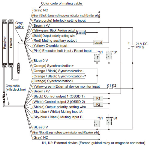
SF4B-□CA-J05
I/O circuit diagrams
<In case of using I/O circuit for PNP output> |
 |
|
* S1
Switch S1
- Emission halt input / Reset input
For manual reset
Vs to Vs – 2.5 V (sink current 5 mA or less): Emission halt (Note)
Open: Emission
For automatic reset
Vs to Vs – 2.5 V (sink current 5 mA or less): Emission (Note)
Open: Emission halt
- Interlock setting input, Override input, Muting input A / B, External device monitor input
Vs to Vs – 2.5 V (sink current 5 mA or less): Valid (Note)
Open: Invalid
- Large multi-purpose indicator input
0 to +1.5 V (source current 5 mA or less): Lights up, Open: Turns OFF
|
| Note: |
Vs is the applying supply voltage. |
<In case of using I/O circuit for NPN output> |
 |
|
* S1
Switch S1
- Emission halt input / Reset input
For manual reset
0 to +1.5 V (source current 5 mA or less): Emission halt
Open: Emission
For automatic reset
0 to +1.5 V (source current 5 mA or less): Emission
Open: Emission halt
- Interlock setting input, Override input, Muting input A / B, External device monitor input
0 to +1.5 V (source current: 5 mA or less): Valid, Open: Invalid
- Large multi-purpose indicator input
0 to +1.5 V (source current 5 mA or less): Lights up, Open: Turns OFF
|
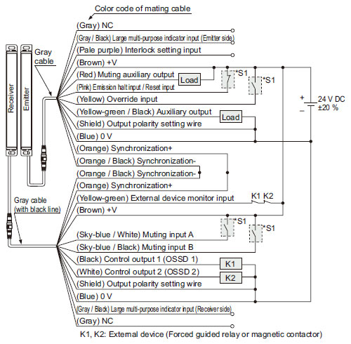
Connection examples
Muting control components: Interlock function "disabled (automatic reset)", external device monitoring function "enabled"
<In case of using I/O circuit for PNP output> |
 |
|
*S1
Switch S1
- Emission halt input / Reset input
For automatic reset Vs to Vs – 2.5 V (sink current 5 mA or less): Emission (Note)
Open: Emission halt
For manual reset Vs to Vs – 2.5 V (sink current 5 mA or less): Emission halt (Note)
Open: Emission
- Muting input A / B, Override input
Vs to Vs – 2.5 V (sink current 5 mA or less): Valid (Note), Open: Invalid
|
| Note: |
Vs is the applying supply voltage. |
The diagram at up shows the configuration when using PNP output, interlock function "disabled (automatic reset)" and external device monitoring function "enabled".
In case of setting the interlock function to "enabled (manual reset)"
- When the interlock function is set to )"Enable (manual reset),)" the override function cannot be used.
|
 |
|
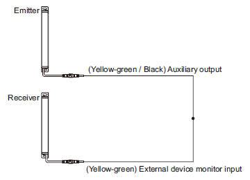
In case of setting the external device monitoring function to "disabled" |
 |
|
<In case of using I/O circuit for NPN output>
*S1
Switch S1
- Emission halt input / Reset input
For automatic reset 0 to +1.5 V (source current 5 mA or less): Emission, Open: Emission halt
For manual reset 0 to +1.5 V (source current 5 mA or less): Emission halt, Open: Emission
- Muting input A / B, Override input
0 to + 1.5 V (source current 5 mA or less): Valid, Open: Invalid
|
The diagram at up shows the configuration when using NPN
output, interlock function "disabled (automatic reset)" and external device monitoring function "enabled".
In case of setting the interlock function to "enabled (manual reset)"
- When the interlock function is set to "Enable (manual reset)," the override function cannot be used.
|
 |
|
In case of setting the external device monitoring function to "disabled" |
 |
|
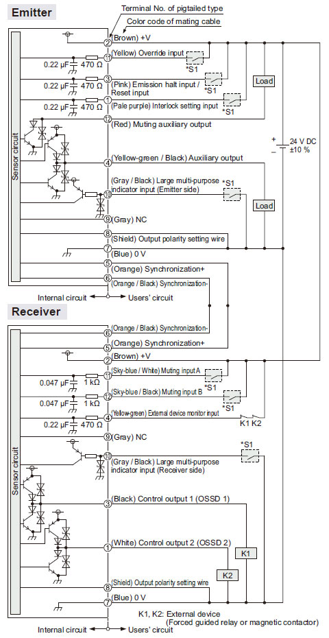
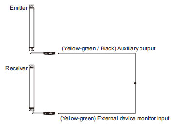
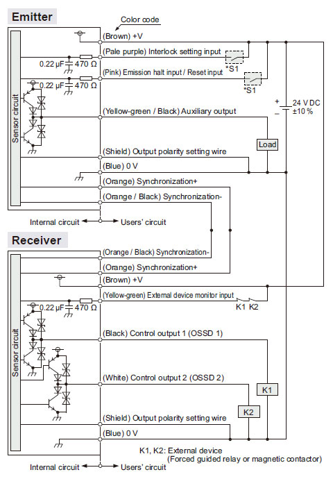
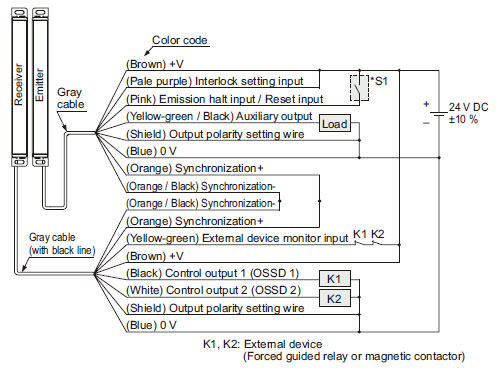
SF4B-□C
I/O circuit diagrams
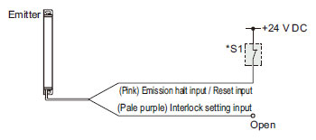
<In case of using I/O circuit for PNP output> |
 |
|
*S1
Switch S1
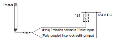
- Emission halt input / Reset input
For manual reset
Vs to Vs – 2.5 V (sink current 5 mA or less): Emission halt (Note)
Open: Emission
For automatic reset
Vs to Vs – 2.5 V (sink current 5 mA or less): Emission (Note)
Open: Emission halt
- Interlock setting input
Vs to Vs – 2.5 V (sink current 5 mA or less): Valid (Note)
Open: Invalid
|
| Note: |
Vs is the applying supply voltage. |
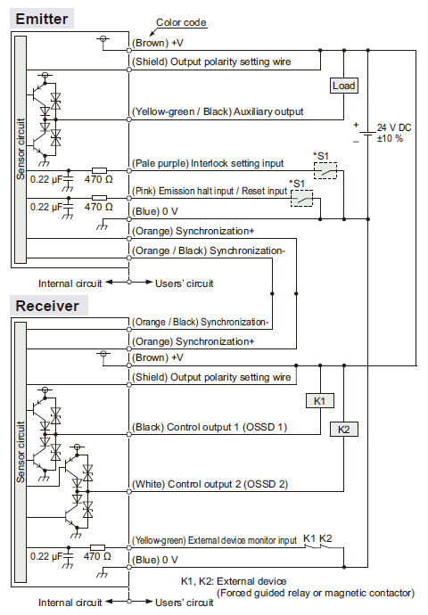
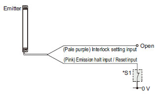
<In case of using I/O circuit for NPN output> |
 |
|
*S1
Switch S1
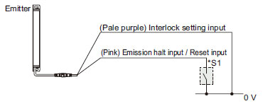
- Emission halt input / Reset input
For manual reset
0 to +1.5 V (source current 5 mA or less): Emission halt
Open: Emission
For automatic reset
0 to +1.5 V (source current 5 mA or less): Emission
Open: Emission halt
- Interlock setting input
0 to +1.5 V (source current 5 mA or less): Valid, Open: Invalid
|
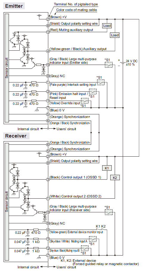
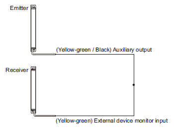
Connection examples
Interlock function "enabled (manual reset)", external device monitoring function "enabled"
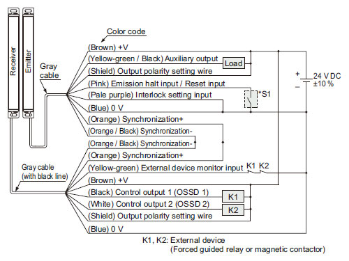
<In case of using I/O circuit for PNP output> |
 |
|
*S1
Switch S1
- Emission halt input / Reset input
For manual reset
Vs to Vs – 2.5 V (sink current 5 mA or less): Emission halt (Note)
Open: Emission
For automatic reset
Vs to Vs – 2.5 V (sink current 5 mA or less): Emission (Note)
Open: Emission halt
- Interlock setting input
Vs to Vs – 2.5 V (sink current 5 mA or less): Valid (Note)
Open: Invalid
|
| Note: |
Vs is the applying supply voltage. |
The diagram at up shows the configuration when using PNP output, interlock function "enabled (manual reset)" and external device monitoring function "enabled".
In case of setting the interlock function to "disabled(automatic reset)" |
 |
|
In case of setting the external device monitoring function to "disabled" |
 |
|
<In case of using I/O circuit for NPN output> |
 |
|
*S1
Switch S1
- Emission halt input / Reset input
For manual reset
0 to +1.5 V (source current 5 mA or less): Emission halt
Open: Emission
For automatic reset
0 to +1.5 V (source current 5 mA or less): Emission
Open: Emission halt
- Interlock setting input
0 to +1.5 V (source current 5 mA or less): Valid, Open: Invalid
|
The diagram at up shows the configuration when using NPN
output, interlock function "enabled (manual reset") and external
device monitoring function "enabled".
In case of setting the external device monitoring function to "disabled" |
 |
|
In case of setting the external device monitoring function to "disabled" |
 |
|
SF-C13
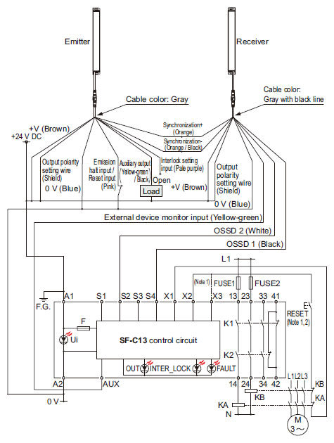
SF4B-□C wiring diagrams (Control Category 4)
For PNP output (minus ground)
- Connect the safety light curtain control outputs OSSD 1 and
OSSD 2 to S1 and S2 respectively.
|
 |
| KA, KB: |
External device
(Forced guided relay or magnetic contactor) |
| Notes: 1) |
The above diagram is when using manual reset. If automatic reset is used, disconnect the lead from X2 and connect it to X3. In this case, a reset (RESET) button is not needed. |
| Notes: 2) |
Use a momentary-type switch as the reset (RESET) button. |
|
|
For NPN output (plus ground)
- Connect the safety light curtain control outputs OSSD 1 and
OSSD 2 to S4 and S2 respectively and ground the + side.
|
 |
| KA, KB: |
External device
(Forced guided relay or magnetic contactor) |
| Notes: 1) |
The above diagram is when using manual reset. If automatic reset is used, disconnect the lead from X2 and connect it to X3. In this case, a reset (RESET) button is not needed. |
| Notes: 2) |
Use a momentary-type switch as the reset (RESET) button. |
|
|
Wiring diagram: SF-C13 control unit
For PNP output (minus to ground)
- Connect the control output 1 (OSSD1) to S1 and the control output 2 (OSSD2) to S2.
|
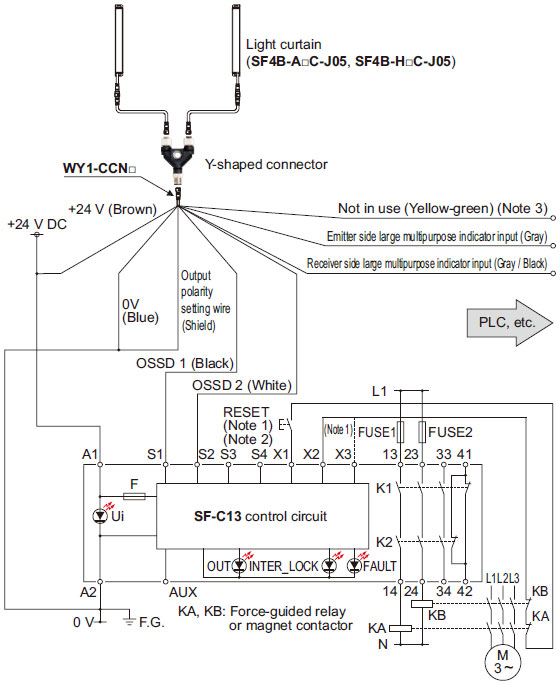 |
Notes:
| 1) |
The above design is when using manual reset. If automatic reset is used, disconnect the lead wire from X2 and connect it to X3.
In this case, a reset (RESET) button is not needed. |
| 2) |
Use a momentary-type switch as the reset (RESET) button. |
| 3) |
Unused wires must be insulated. |
|
|
For NPN output (plus to ground)
- Connect the control output 1 (OSSD1) to S4 and the control output 2 (OSSD2) to S2.
|
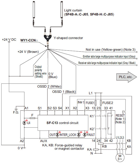 |
Notes:
| 1) |
The above design is when using manual reset. If automatic reset is used, disconnect the lead wire from X2 and connect it to X3.
In this case, a reset (RESET) button is not needed. |
| 2) |
Use a momentary-type switch as the reset (RESET) button. |
| 3) |
Unused wires must be insulated. |
|
|
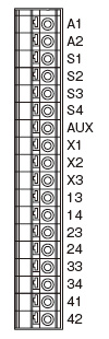
Terminal arrangement diagram
|
|
| Terminal |
Description |
| A1 |
+24 V DC |
| A2 |
0 V |
| S1 to S4 |
Safety light curtain control output (OSSD) input terminal |
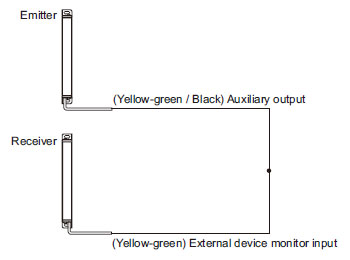
| AUX |
Semiconductor auxiliary output |
| X1 |
Reset output terminal |
| X2 |
Reset input terminal (Manual) |
| X3 |
Reset input terminal (Automatic) |
| 13-14、23-24、33-34 |
Safety output (NO contact × 3) |
| 41-42 |
Auxiliary output (NC contact × 1) |
| When wiring connections to the safety light curtain, you are responsible for providing a terminal block. |
|
Return to top
Return to top

 Business
> Industrial Devices
> Automation Controls Top
> FA Sensors & Components
> Sensors
> Light Curtains / Safety Components
> Compact Safety Light Curtain[Type4 PLe SIL3] SF4B-C
> I/O Circuit and Wiring diagrams
Business
> Industrial Devices
> Automation Controls Top
> FA Sensors & Components
> Sensors
> Light Curtains / Safety Components
> Compact Safety Light Curtain[Type4 PLe SIL3] SF4B-C
> I/O Circuit and Wiring diagrams