[System Maintenance Notice]
Due to ongoing system maintenance, the site search and specification search functions are temporarily unavailable. We apologize for any inconvenience this may cause and appreciate your understanding.
【Notification of Manufacturer Change for Panasonic Industrial Devices SUNX Products and Panasonic Industrial Devices SUNX Tatsuno Products】
From April 1, 2024, the terms "Panasonic Industrial Devices SUNX Co., Ltd." and "Panasonic Industrial Devices SUNX Tatsuno Co., Ltd."
in this page and in the manuals and other documents to be downloaded will all be replaced with "Panasonic Industry Co., Ltd." and applied accordingly.

 Business
> Industrial Devices
> Automation Controls Top
> FA Sensors & Components
> Static Control Devices
> Static Control Devices
> Pulse AC Method Area Ionizer ER-X
> Cautions For Use
Business
> Industrial Devices
> Automation Controls Top
> FA Sensors & Components
> Static Control Devices
> Static Control Devices
> Pulse AC Method Area Ionizer ER-X
> Cautions For Use
Pulse AC Method Area Ionizer ER-X
|
Cautions For Use
- Never use this product as device for personnel protection.
- In case of using devices for personnel protection, use products which meet laws or standards, such as OSHA, ANSI or IEC etc., for personnel protection applicable in each region or country.
- This product produces high voltages.
- Do not use this product in places where there may be a danger of flammable or combustible items being present.
- To prevent electric shock and to conduct proper discharge, be sure to ground a frame ground (F.G.) terminal of a controller.
- Do not place hands near the discharge needle. Doing so may cause electric shock.
- Since the tip of the discharge needle is sharp, take sufficient care in handling the discharge needle, or injuries may result.
- The high-voltage cable between the head and the high-voltage unit must be fixed and the minimum bend radius is less than R30 mm R1.181 in. In case of using at the bend radius R30 mm R1.181 in or less and using at moving part may cause fire and break down, etc. of the high-voltage cable.
- Clean the discharge needle regularly (about once a week). Otherwise, optimum charge removal performance may not be achieved, and accidents or operating problems may occur.
- If this product is used in a confined space, ozone emitted from this product may be detrimental. Be sure to provide ventilation.
- Do not direct ionized air toward the face. Ozone may cause irritation to places such as the nose and throat.
- When the product has been used under very high or low temperatures, do not touch the product with a bare hand. Failure to observe this caution can result in burn or injury. Be sure to let the product cool sufficiently when touching the product for maintenance or other purposes.
- When using as a CSA and UL compliant product, use a CLASS 2 CSA/UL certified power supply, or a CSA/UL certified power supply that has been evaluated as a Limited Power Source as specified in CAN/CSA-C22.2 No.60950-1/UL60950-1.
- This product has been developed / produced for industrial use only.
- Do not use this product for purposes other than electric charge removal.
- Do not use this product in environments which are outside the specification range, otherwise operating problems or damage may occur. In addition, the operating life of the product may become significantly reduced.
- This product is a precision device. Do not apply a shock to it by dropping, for example. Accidents or operating problems may occur.
- Never disassemble, repair or modify this product. Accidents or operating problems may occur.
- Do not throw this product in fire. It may explode or toxic fumes may be generated.
- Do not run the wires together with high-voltage lines or power lines or put them in the same raceway. This can cause malfunction due to induction.
- Verify that the supply voltage variation is within the rating.
- In case using switching regulator, be sure to connect F.G. terminal.
- When connecting / removing the head or performing wiring or inspection work, be sure to turn off the power first. Not doing so may result in accidents, electric shock or operating problems.
- After connecting the cables, check that the connections are correct before turning on the power. If the cables are connected incorrectly, operating problems or accidents may occur.
- Do not use a cable with any damage such as cracks or splitting. Risk of accidents and failure.
- Avoid use in a location with significant steam or dust, or in a location where the product may come in direct contact with water, oil, or welding spatter.
- Do not touch the discharge needle with hard objects such as tools. If the discharge needle becomes broken, it will not provide sufficient charge removal performance, and moreover operating problems or accidents may occur.
- During installation, fasten the product securely. If it is not securely fastened or it is subjected to continuous vibration or shock, accidents or operating problems may result.
- Power cable that are 0.15mm2 or more and 30 m 98.425 ft or less in total length for wiring. Also, keep the wiring as short as possible in order to prevent noise.
- When disposing of this product, treat it appropriately as industrial waste.
- After starting discharge, it takes 30 minutes approx. for charge removal performance to stabilize. Therefore, wait 30 minutes before adjusting ion balance.
- Use the correct combination of head, discharge needle unit and controller.
Identification of previous-type and new-type controllers and combination with the head
|
| Combination | New-type controller (Note) |
Previous-type controller (Note) |
||||
|---|---|---|---|---|---|---|
| Produced from April 2016 on |
Produced from April 2014 and before April 2016 |
Produced before March 2014 | ||||
 |
 |
 |
||||
| Head | Spot type |
ER-X001 | OK | OK | Cannot be used | |
| Bar type |
ER-X008 | OK | OK | Cannot be used | ||
| ER-X016 | OK | |||||
| ER-X032 | ||||||
| ER-X048 | ||||||
| ER-X064 | ||||||
| High and Low temperature resistant |
ER-X008HC | OK | Cannot be used | Cannot be used | ||
| ER-X016HC | OK | |||||
| ER-X032HC | ||||||
| ER-X048HC | ||||||
| ER-X064HC | ||||||
| Note: | The layout of the power supply connector pins differ between new-type controllers and previous-type controllers.For details refer to I/O CIRCUIT AND WIRING DIAGRAMS. |
|---|
Mounting
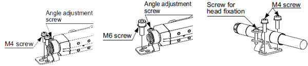
Head installation
- Using 2 M4 screws or 1 M6 screw, mount the head onto the equipment housing.
- Loosen the angle adjustment screw, adjust the head angle, and then fasten the head with the tightening torque of 0.5 N∙m or less.
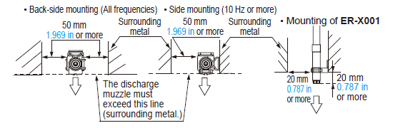
- Position the head mounting bracket of the ER-X001 at least 20 mm 0.787 in away from the tip of the head. The tightening torque for the head fixing screw must be 0.5 N∙m or less.
After mounting and setting up the head, set the controller according to the procedures described in the instruction manual in order to properly remove electrical charge.
|
Notes:
| 1) | Be sure to ground the equipment housing onto which the head is mounted. |
|---|---|
| 2) | The distance between the head and the charge removing object should be 30 mm 1.181 in or more. If the static buildup of the charge removing object is 30 kV or more, set the distance to 50 mm 1.969 in or more. |
| 3) | If there is metal near the head or between the head and the charge removing object, ion is absorbed, hindering appropriate static removal. Install the head under the following installation condition. |
| 4) | In case using the side mounting, the discharge frequency should be 10 Hz or more. |
|
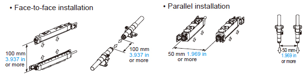
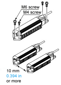
| 5) | When installing two or more heads set the same frequency and keep the distance as below. In face to face or parallel using different frequency, keep the distance between the heads 400 mm
15.748 in or more. When installing the heads face to face, install heads in distance that the heads can perform the charge removal of a side of the object individualy. |
|---|
|
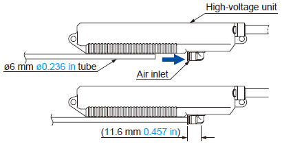
High-voltage unit installation
Notes:
|
 |
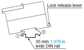
Controller installation
- Mount the controller on a 35 mm 1.378 in wide DIN rail or using M4 screws.
<When mounting on a DIN rail>
|
 |
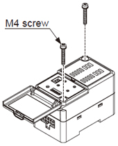
<When mounting using M4 screws>
|
 |
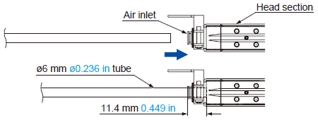
Piping
- Air supplied to this product will reduce contamination of the discharge needle and improve the charge removal speed.
- The outer diameter of the air tube to fit to the air inlet portion of this product should be ø6 mm ø0.236 in.
- Make sure that clean air (air containing no water, no oil and no dust) should be supplied.
- Since the pressure will drop when the air piping from the main pressure supply is extended or pneumatic components (e.g., needle valve, speed controller, mini filter) are added, keep an eye on the pressure supply to the ionizer making sure it is not in short supply. For the pneumatic components, select those that can accommodate the air supply flow rate.
|
|
|
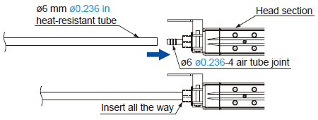
| Note: | After inserting the tube into the joint of this product, always make sure that the tube is all the way in and securely inserted. Insufficient tube insertion will cause air leakage. |
|---|
BY EMAIL


Requests to customers (Automation Control Components & Industrial Device) [Excluding specific product]
Requests to customers (Automation Control Components & Industrial Device) [For specific product]
Requests to customers (FA Sensors & Components [Excluding motors])
Requests to customers (Dedicated to industrial motors)
- COMPONENTS & DEVICES
- FA SENSORS & COMPONENTS
- Fiber Sensors
- Photoelectric Sensors / Laser Sensors
- Micro Photoelectric Sensors
- Light Curtains / Safety Components
- Area Sensors
- Inductive Proximity Sensors
- Particular Use Sensors
- Sensor Options
- Wire-Saving Systems
- Programmable Controllers / Interface Terminal
- Human Machine Interface
- Pressure Sensors / Flow Sensors
- Measurement Sensors
- Static Control Devices
- Laser Markers / 2D Code Readers
- Machine Vision System
- Energy Management Solutions
- Timers / Counters / FA Components
- MOTORS
![]()