[System Maintenance Notice]
Due to ongoing system maintenance, the site search and specification search functions are temporarily unavailable. We apologize for any inconvenience this may cause and appreciate your understanding.

 Business
> Industrial Devices
> Automation Controls Top
> Components & Devices
> Connectors
> Automotive Connectors
> CF1
> Rating/Performance
Business
> Industrial Devices
> Automation Controls Top
> Components & Devices
> Connectors
> Automotive Connectors
> CF1
> Rating/Performance
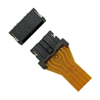
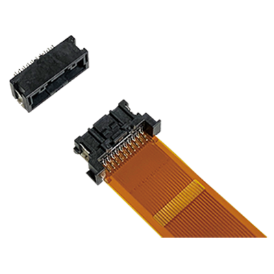
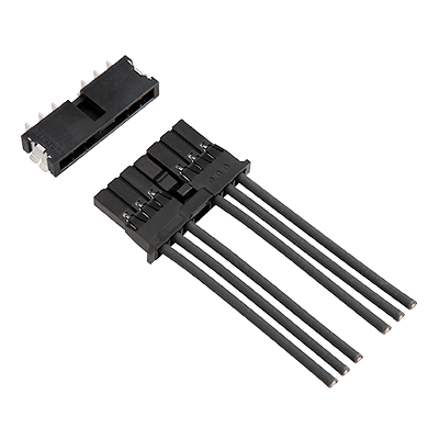
CF1
For Automotive Application with 125°C heat resistance, Connectors for board-to-FPC
|
 |

Features
- ●
Suitable for automotive applications that require vibration and heat resistance (125℃) characteristics.
- ●
“Anti-misoperation bridge structure” prevents unintended operation of mating lock.
- ●
FPCs and boards can be directly connected without relay wiring harnesses
- ●
Contact reliability is preserved by double-sided contact structure
- ●
Inertia lock construction prevents half-mating (4 pins only)
Applications
- ●
Connection of board and FPC in DRL/rear lamp
- ●
Connection of board and FPC in BMS
|
Characteristics
| Item | Specifications | Conditions | |
|---|---|---|---|
| Electrical characteristics |
Rated current | 2.0 A/pin contact | Maximum current can be applied to one contact. (Except for the capacity of FPC.) |
| Rated voltage | 50 V DC | ||
| Dielectric strength | 1,000 V AC for 1 min | Detection current: 1 mA (No short or damage) | |
| Insulation resistance | Min. 100 MΩ | Using 500 V DC megger (1 min) | |
| Contact resistance | Max. 20 mΩ (Initial) Max. 40 mΩ (after test) |
Except FPC conductor resistance. Measured at 10 mA DC |
|
| Mechanical characteristics |
Insertion force | Max. 36.0 N (Initial stage. No difference by number of pins.) | |
| Removal force | Max. 18.0 N (Initial stage. 4 pins) Max. 23.0 N (Initial stage. 6 pins) Max. 28.0 N (Initial stage. 8 pins) Max. 33.0 N (Initial stage. 10 pins) |
Measured by removal of housing lock. | |
| Housing lock force | Min. 50.0 N (Initial stage. No difference by number of pins.) | ||
| Environmental characteristics |
Temperature and humidity of ambient storage and transportation |
-40 to +125°C (Including temperature rise when applying current) (Storage and transportation temperature is -40 to +50°C in a packing state.) *1 |
No icing. No condensation. |
| Soldering heat resistance | The initial specification must be satisfied electrically and mechanically | Max. peak temperature of 260°C Reflow soldering: Max. 2 times (Temperature at connector terminal portion) |
|
| Thermal shock resistance (Receptacle and plug mated) |
After 500 cycles, Contact resistance: Max. 40 mΩ |
 *Vapor phase |
|
| Humidity resistance (Receptacle and plug mated) |
After 96 hours, Contact resistance: Max. 40 mΩ Insulation resistance: Min. 100 MΩ |
Bath temperature 60 ±2°C Humidity 90% RH |
|
| Heat resistance (Receptacle and plug mated) | After 120 hours, Contact resistance: Max. 40 mΩ | Bath temperature 125 ±2°C | |
| Vibration resistance (Receptacle and plug mated) |
Current shut off should not exceed 1 μs during vibration test. (Contact resistance: Max. 40 mΩ) |
Acceleration: 44 m/s² Frequency: 20 to 200 Hz Sweep time: 3 min/cycle Testing tool: Refer to Fig.1 *2 Direction: 3 axes (X, Y, Z) (Different samples are used for each direction.) Time: 3 h Detection current: 10 mA |
|
| Shock resistance (Receptacle and plug mated) |
Current shut off should not exceed 1 μs during shock test. | Acceleration: 981 m/s² Operation time: 6 ms Testing tool: Refer to Fig.1 *2 Direction: 6 direction (±X, ±Y, ±Z) (Different samples are used for each direction.) Number: 3 times Detection current: 10 mA |
|
| Lifetime characteristics |
Insertion and removal life |
10 times (Contact resistance: Max. 40 mΩ) | Speed: 25 mm/min |
| Solder paste thickness | The initial specification must be satisfied electrically and mechanically | Recommendation t=0.15 mm | |
| *1.As the humidity range differs depending on the ambient temperature, the humidity range indicated below should be used. This temperature and humidity range does not guarantee permanent performance. |
 |
| *2. Fig.1 |
 |
Material and surface treatment
Receptacle
| Part name | Material | Color | Surface treatment |
|---|---|---|---|
| Body | LCP resin (UL94V-0) | Black | - |
| Post | Copper alloy | - | Contact portion: Sn plating over nickel Soldering portion: Sn plating over nickel |
| Metal tab | Copper alloy | - | Soldering portion: Sn plating over nickel |
Plug
| Part name | Material | Color | Surface treatment |
|---|---|---|---|
| Housing | LCP resin (UL94V-0) | Black | - |
| Contact | Copper alloy | - | Contact portion: Sn plating over nickel Soldering portion: Sn plating over nickel |
| Metal tab | Copper alloy | - | Soldering portion: Sn plating over nickel |
|
BY EMAIL
- U.S.A.
- +1-800-344-2112
- Europe
- +49-89-45354-1000
- China
- +86-10-59255988
- Singapore
- +65-6299-9181


Requests to customers (Automation Control Components & Industrial Device) [Excluding specific product]
Requests to customers (Automation Control Components & Industrial Device) [For specific product]
Requests to customers (FA Sensors & Components [Excluding motors])
Requests to customers (Dedicated to industrial motors)
- COMPONENTS & DEVICES
- FA SENSORS & COMPONENTS
- Fiber Sensors
- Photoelectric Sensors / Laser Sensors
- Micro Photoelectric Sensors
- Light Curtains / Safety Components
- Area Sensors
- Inductive Proximity Sensors
- Particular Use Sensors
- Sensor Options
- Wire-Saving Systems
- Programmable Controllers / Interface Terminal
- Human Machine Interface
- Pressure Sensors / Flow Sensors
- Measurement Sensors
- Static Control Devices
- Laser Markers / 2D Code Readers
- Machine Vision System
- Energy Management Solutions
- Timers / Counters / FA Components
- MOTORS
![]()