

 Business
> Industrial Devices
> Automation Controls Top
> Components & Devices
> Relays / Couplers
> Panasonic Products for Energy Management
> features
Business
> Industrial Devices
> Automation Controls Top
> Components & Devices
> Relays / Couplers
> Panasonic Products for Energy Management
> features
Panasonic Products for Energy Management
Features for DC Side


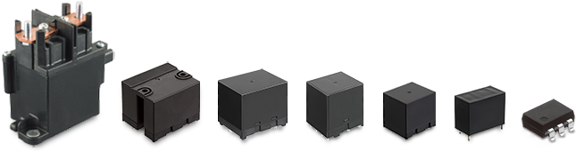
EP Relays
EP Relay Features for DC Side
The EP relay is a power relay that enables DC high voltage and a high current interruption in small size.
Below listed are features compared to DC contactor of existing products generally used in the DC high voltage area.
Sealed construction keeps the arc inside
Safety
Construction
Arc
Free arc space
Space saving
Arc space is necessary for existing products and cannot use adjacent mounting.
The capsule contact construction is lled with H2 gas which provides a large cuto capacity with a small contact gap.
Small
The arc is cooled and intercepted rapidly by the hydrogen mixed gas in the capsule contact.
Hydrogen gas
Operation explanation (interception mechanism)
power to relay is ON.
Stationary
contact
Movable
contact
Stationary
contact
Arc is generated when power to relay is cut.
Arcing
Arc is attracted to the inner wall of sealed capsule contact, preventing arc from running side.
Arcing
Due to external magnetic force, arc runs horizontally over contact surface.
Arcing
EP Relay Estimated Life (Cycles) for DC Side
Reference data
Notes: In case of using over the rating, the data is only reference use. Please test the actual condition befor use.
- 110A type
- 220A type
- 380A type
- 4200A type
- 5300A type
HE-V Relays
HE-V Relay Features for DC Side
The HE-V relay is a miniature power relay that can conduct and cut off high DC voltage or high currents. Using a 2 Form A contact, it is capable of both plus and minus line cutoff on the DC side.
Using a blow-out magnet mechanism and serial contact connection, the required arc and gap length is maintained for high DC voltage cutoff.
Over 3.8 mm contact gap
(for each 1 Form A contact)
Safety
Construction
Arc
Miniature size attained compared to using two 1 Form A contact relays. Enhanced freedom of design
Small
Solar inverter
*Serial connection example
Reduction of power consumption is achieved by reducing the coil holding voltage after applying nominal coil voltage for at least 100 ms during relay operation.
Energy-saving
| Nominal operating power | Ratio in which coil holding voltage can be decreased | Power consumption when coil holding voltage decreases |
| 1,920mW | 33%V of rated coil voltage | approx. 210mW |
Operation explanation (interception mechanism)
Power to relay is ON.
Arc is generated when power to relay contact is cut.
The arc extends inside the arc extinction space and completes cutoff. The arc does not get out.
The arc extends by applying transverse eld.
Inside arc extinction space
Contribute to energy saving with reduced coil holding voltage
In existing products, nominal coil voltage had to be applied to the coil side. However HE-V Relay will be operated with reduced coil voltage (coil holding voltage *1), so that lower power consumption could be achieved.
Reduce the coil holding voltage after applying the rated coil voltage for 100 ms or longer in that way you could reduce the energy consumption.
|
Condition: Max.contact carrying current at 20°C
*1 Coil holding voltage is the coil voltage after 100ms following application of the rated coil voltage. |
HE-V Relay 15V  |
How to reduce coil holding voltage
To reduce coil holding voltage, one way is to set nominal coil voltage over 100ms. However you shall have similar result using below way also.
1. Sample: HEV2aN-P-DC9V (9V type)
2. Circuit 
3. Recommend condition (Ambient temperature: 20˚C)
| Coil impress voltage | Coil holding voltage | R (Relay) | C | r | Inrush time | Time until nominal voltage | Voltage in operate time | Operate time | ||
|---|---|---|---|---|---|---|---|---|---|---|
| * Time until nominal voltage is more than 1.5 times of operate voltage. The method of reduce coil holding voltage is only reference. Not guaranteed. Please check under the most stringent conditions in the actual application. | ||||||||||
| [V] | [%V] | [V] | [%V] | [Ω] | [µF] | [Ω] | [ms] | [ms] | [V] | [ms] |
| 12 | 133.3 | 4.5 | 50.0 | 42.2 | 640 | 70.3 | 76.5 | 18.0 | 10.0 | 11.85 |
●Wave of coil voltage
HE-V Relay Estimated Life (Cycles) for DC Side
Reference data
Notes: In case of using over the rating, the data is only reference use. Please test the actual condition befor use.
- 1Contact connected in series
- 21 Form A series
Recommended circuit
Positive polarity of load should be connected to pin 1 and pin 3, refer to the following circuit schematics.
- 1. Each 1 Form A contact connected in series (Bottom view)
- 2. 1 Form A contact only (Bottom view)
Catalog Download
|
|
Title | Language | File size | Update |
|---|---|---|---|---|
| エネルギーマネジメント向け商品のご提案 | JP | 5.1MB | December 6, 2022 | |
| Panasonic Industry Products for Energy Management | EN | 4.8MB | December 6, 2022 |
If you have any questions about our products, feel free to email or call us!

Requests to customers (Automation Control Components & Industrial Device) [Excluding specific product]
Requests to customers (Automation Control Components & Industrial Device) [For specific product]
Requests to customers (FA Sensors & Components [Excluding motors])
Requests to customers (Dedicated to industrial motors)
- COMPONENTS & DEVICES
- FA SENSORS & COMPONENTS
- Fiber Sensors
- Photoelectric Sensors / Laser Sensors
- Micro Photoelectric Sensors
- Light Curtains / Safety Components
- Area Sensors
- Inductive Proximity Sensors
- Particular Use Sensors
- Sensor Options
- Wire-Saving Systems
- Programmable Controllers / Interface Terminal
- Human Machine Interface
- Pressure Sensors / Flow Sensors
- Measurement Sensors
- Static Control Devices
- Laser Markers / 2D Code Readers
- Machine Vision System
- Energy Management Solutions
- Timers / Counters / FA Components
- MOTORS
![]()