[System Maintenance Notice]
Due to ongoing system maintenance, the site search and specification search functions are temporarily unavailable. We apologize for any inconvenience this may cause and appreciate your understanding.

 Business
> Industrial Devices
> Automation Controls Top
> Components & Devices
> Relays / Couplers
> PhotoIC Coupler
> PhotoIC Coupler Cautions for Use
Business
> Industrial Devices
> Automation Controls Top
> Components & Devices
> Relays / Couplers
> PhotoIC Coupler
> PhotoIC Coupler Cautions for Use
Cautions for Use of PhotoIC Couplers
SAFETY WARNINGS
- Do not use the product under conditions that exceed the range of its specifications. It may cause overheating, smoke, or fire.
- Do not touch the recharging unit while the power is on. There is a danger of electrical shock. Be sure to turn off the power when performing mounting, maintenance, or repair operations on the device (including connecting parts such as the terminal board and socket).
- Check the connection diagrams in the catalog and be sure to connect the terminals correctly. Erroneous connections could lead to unexpected operating errors, overheating, or fire.
Cautions for Use of PhotoIC Couplers
■Please visit our Automation Controls Products web site and refer to the caution for use and the explanations of technical terms.
■About derating design
Derating is significant factor concerning on reliable design (product life). When the coupler is used continuously at upper limit of absolute maximum ratings (high temperature, high humidity, high current, high voltage, etc.), reliability may be lower significantly. Therefore, please derate sufficiently below the absolute maximum ratings and evaluate the coupler under the actual condition.
■Wire connection
Please check the internal connection diagram in the catalog or specification, and connect the terminals correctly. If device is energized with short-circuit or any wrong connection, it may cause circuit damage by inner parts destruction, unexpected malfunction, abnormal heat, fire, and so on.
■Bypass capacitor
Bypass capacitor of 0.1 μF is used between Vcc and GND near the coupler. Also, ensure that the distance between the leads of the coupler and capacitor is no more than 10 mm. Failure to provide the bypass may impair the switching property.
■Deterioration and destruction caused by discharge of static electricity
This phenomenon is generally called static electricity destruction, and occurs when static electricity generated by various factors is discharged while the coupler terminals are in contact, producing internal destruction of the element.
To prevent problems from static electricity, the following precautions and measures should be taken when using your device.
- 1. Employees handling the coupler should wear anti-static clothing and should be grounded through protective resistance of 500 kΩ to 1 MΩ.
- 2. A conductive metal sheet should be placed over the worktable. Measuring instruments and jigs should be grounded.
- 3. When using soldering irons, either use irons with low leakage current, or ground the tip of the soldering iron.
(Use of low-voltage soldering irons is also recommended.) - 4. Devices and equipment used in assembly should also be grounded.
- 5. When packing printed circuit boards and equipment, avoid using high-polymer materials such as foam styrene, plastic, and other materials which carry an electrostatic charge.
- 6. When storing or transporting the coupler, the environment should not be conducive to generating static electricity (for instance, the humidity should be between 45 and 60%), and the coupler should be protected using conductive packing materials.
■Caution for applying supply voltage
Just after supplying voltage, please note that current in the coupler will be not constant until circuit stability.
■Soldering
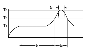
1.IR (Infrared reflow) soldering method
In case of automatic soldering, following conditions should be observed.
(recommended condition reflow: Max. 2 times, measurement point: soldering lead)
|
||
|
T1 = 150 to 180 °C |
2.Others soldering methods
Other soldering methods (VPS, hot-air, hot plate, laser heating, pulse heater, etc.) affect the coupler characteristics differently, please evaluate the coupler under the actual usage.
3.Manual soldering method
Soldering: Max. 350 °C, within 3 s, electrical power 30 to 60 W
■Notes for mounting
- 1.When different kinds of packages are mounted on PC board, the temperature rise at soldering lead is highly dependent on package size. Therefore, please set the lower temperature soldering condition than above condition, and confirm the temperature condition of actual usage before soldering.
- 2.When soldering condition is out of recommendation, the coupler characteristics may be adversely affected. It may occur package crack or bonding wire breaking because of thermal expansion unconformity and resin strength reduction. Please contact us about the propriety of the condition.
- 3.Please confirm the heat stress by using actual board because it may be changed by board condition or manufacturing process condition.
- 4.Solder creepage, wettability, or soldering strength will be affected by the soldering condition or used solder type. Please check them under the actual production condition in detail.
- 5.Please apply coating when the coupler returns to the room temperature.
■Cleaning solvents compatibility
Cleaning the solder flux should use the immersion washing with an cleaning solvent (Asahiklin AK-225). If you have to use ultrasonic cleaning, please adopt the following conditions and check that there are no problems in the actual usage.
- Frequency: 27 to 29 kHz
- Ultrasonic output: No greater than 0.25 W/cm2 *
- Cleaning time: 30 s or less
- Others: Float PC board and the device in cleaning solvent to prevent from contacting the ultrasonic vibrator.
* Note: Applies to unit area of ultrasonic output for ultrasonic baths.
■Transportation and storage
- 1.Extreme vibration during transport may deform the lead or damage the coupler. Please handle the outer and inner boxes with care.
- 2.Inadequate storage condition may degrade soldering, appearance and characteristics.
The following storage conditions are recommended:
- Temperature: 0 to 45 °C
- Humidity: Max. 70% RH
- Atmosphere: No harmful gasses such as sulfurous acid gas and not dusty.
- 3.In case the heat stress of soldering is applied to the coupler which absorb moisture inside of its package, the evaporation of the moisture increases the pressure inside the package and it may cause the package blister or crack. This coupler is sensitive to moisture and it is packed in the sealed moisture-proof package. Please make sure the following condition after unsealing.
* Please use the coupler immediately after unsealing. (within 30 days at 0 to 30 °C and Max. 70% RH)
* If the coupler will be kept for a long time after unsealing, please pack in the another moisture-proof package containing silica gel and store. (Please use within 90 days)
■Water condensation
Water condensation occurs when the ambient temperature changes suddenly from a high temperature to low temperature at high humidity, or the coupler is suddenly transferred from a low ambient temperature to a high temperature and humidity.
Condensation causes the failures such as insulation deterioration. Panasonic Industry does not guarantee the failures caused by water condensation.
The heat conduction by the equipment the coupler is mounted may accelerate inside equipment water condensation. Please confirm no that there are condensation in the worst condition of the actual usage.
(Special attention should be paid when high temperature heating parts are close to the coupler.)
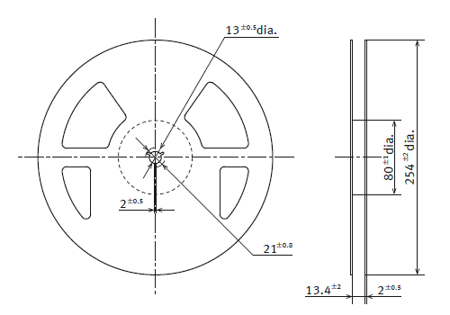
■Coupler packaging format
1. Tape and reel (Unit: mm)
| Tape dimensions | Dimensions of tape reel |
|---|---|

(1) When picked from 1/2-pin side: Part No. APS***1SX (Shown above) |
|
BY EMAIL
- U.S.A.
- +1-800-344-2112
- Europe
- +49-89-45354-1000
- China
- +86-10-59255988
- Singapore
- +65-6299-9181


PhotoIC Coupler
-
20 Mbps type Low input voltage and low power consumption achieved. High speed Photo Coupler with receiver circuit IC. -

50 Mbps type High speed Photo Coupler with receiver circuit IC.
Requests to customers (Automation Control Components & Industrial Device) [Excluding specific product]
Requests to customers (Automation Control Components & Industrial Device) [For specific product]
Requests to customers (FA Sensors & Components [Excluding motors])
Requests to customers (Dedicated to industrial motors)
- COMPONENTS & DEVICES
- FA SENSORS & COMPONENTS
- Fiber Sensors
- Photoelectric Sensors / Laser Sensors
- Micro Photoelectric Sensors
- Light Curtains / Safety Components
- Area Sensors
- Inductive Proximity Sensors
- Particular Use Sensors
- Sensor Options
- Wire-Saving Systems
- Programmable Controllers / Interface Terminal
- Human Machine Interface
- Pressure Sensors / Flow Sensors
- Measurement Sensors
- Static Control Devices
- Laser Markers / 2D Code Readers
- Machine Vision System
- Energy Management Solutions
- Timers / Counters / FA Components
- MOTORS
![]()