[System Maintenance Notice]
Due to ongoing system maintenance, the site search and specification search functions are temporarily unavailable. We apologize for any inconvenience this may cause and appreciate your understanding.

 Business
> Industrial Devices
> Automation Controls Top
> Components & Devices
> Switches
> Snap action Switches
> Snap action Switches Technical Terminology & Cautions for Use
Business
> Industrial Devices
> Automation Controls Top
> Components & Devices
> Switches
> Snap action Switches
> Snap action Switches Technical Terminology & Cautions for Use
Technical Terminology & Cautions for Use (Detection Switches)
Technical Terminology
■Detection Switches
A compact switch equipped with an enclosed micro-gap snap-action contact mechanism that makes a specified motion with a specified force to open/close a circuit, and an actuator outside the enclosure (hereinafter referred to as the switch)
■Actuator
A part of the switch that transmits the received external force to an internal spring mechanism to move the movable contact so that the switch can be opened and closed
■Actuator stopper
A part of the switch to limit the actuator movement in the switch operation direction
■Rated values
Values indicating the characteristics and performance guarantee standards of the snap-action switches. The rated current and rated voltage, for instance, assume specific conditions (type of load, current, voltage, frequency, etc.).
■Mechanical life
The service life when operated at a preset operating frequency without passing electricity through the contacts. (The life test is performed at a switching frequency of 60 times/minute and operating speed of 100 mm/second at the regular cam.)
■Electrical life
The service life when the rated load is connected to the contact and switching operations are performed. (The life test is performed at a switching frequency of 20 times/minute and operating speed of 100 mm/second at the regular cam.)
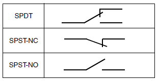
■Contact form
This refers to the components determining the type of application which make up the electrical input/output circuits in the contact.
|
■Insulation resistance
Resistance between non-continuous terminals, each terminal and other exposed metal parts and between each terminal and ground.
■Dielectric
Threshold limit value that a high voltage can be applied to a predetermined measuring location for one minute without causing damage to the insulation.
■Contact resistance
This indicates the electrical resistance at the contact part. Generally, this resistance includes the conductor resistance of the spring and terminal portions.
■Vibration resistance
| Malfunction vibration | : | Vibration range where a closed contact does not open for longer than a specified time due to vibrations during use of the snap-action switches. |
|---|
■Shock resistance
| Shock durability | : | Shock range where the mechanical shocks received during snap-action switches transport and installation do not damage the parts or harm the operating characteristics. |
|---|---|---|
| Malfunction shock | : | Shock range where a closed contact does not open for longer than a specified time due to shocks during use of the snap-action switches. |
Operating Characteristic
Definition of operating characteristic
The main terminological illustrations and meanings which are used with snap-action switches are as follows.
|
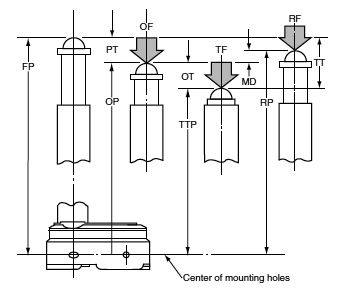
| Classification | Terminology | Symbol | Unit | Varying display method | Starting current |
|---|---|---|---|---|---|
| Force | Operating Force | OF | N | Max. | The force required to cause contact snap-action. It is expressed terms of force applied to the actuator. |
| Release Force | RF | N | Min. | The force to be applied to the actuator at the moment contact snaps back from operated position to total travel position. | |
| Total travel Force | TF | N | Force applied to an actuator required to move from an operating position to a total travel position | ||
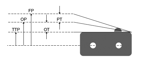
| Movement | Pretravel | PT | mm, degree | Max. | Distance or agree of the actuator movement from free position to operating position. |
| Over travel | OT | mm, degree | Min. | The distance or degree which the actuator is permitted to travel after actuation without any damage to the switching mechanism. | |
| Movement Differential | MD | mm, degree | Max. | The distance or degree from operating position to release position of the actuator. | |
| Total travel | TT | mm, degree | The migration length or the move angle from the free position to total travel position of actuator | ||
| Position | Free Position | FP | mm, degree | Position of the actuator when no force is applied to. | |
| Operating Position | OP | mm, degree | ± | The position of the actuator when the traveling contacts snaps with the fixed contact. | |
| Release Position | RP | mm, degree | The position of the actuator when the traveling contacts snaps back from operating position to its original position. | ||
| Total travel Position | TTP | mm, degree | The stopping position of the actuator after total travel. |
Technical Notes on Mechanical Characteristics
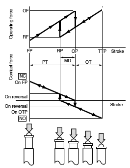
■Actuation Force and Stroke
Adequate stroke setting is the key to high reliability.
It is also important that adequate contact force be ’maintained to ensure high reliability.
For a normally closed (N.C.) circuit, the driving mechanism should be set so that the actuator is normally in the free position.
For a normally open (N.O.) circuit, the actuator should be pressed to 70% to 100% of the specified stroke to absorb possible errors.
If the stroke is set too close to the operating point (OP), this may cause unstable contact,
and in the worst case may cause actuator damage due to inertia of the drive mechanism.
It is advisable that the stroke be adjusted with the mounting plate or driving mechanism.
The figure at right shows a typical example of activation and contact forces varying with stroke. In the vicinity of the OP and RP, the contact force is diminished, causing chatter and contact bounce immediately before or after reversal. For this reason, use the switch while giving due consideration to this. This also causes the snap action switch to be sensitive to vibration or shock.
|
■Changes in Operation Characteristics
Exercise design care so that malfunctions will not occur if the operating characteristics vary by as much as 20% from, rated values.
<Example>
In the OF max. 0.98N specification for FS snap-action switches,
the allowable max. is 0.98 N × (100%+20%) = 1.18 N
In the RF min. 0.15 N min. specification,
the allowable min. 0.15 N × (100%–20%) = 0.12 N
■Mechanical Conditions for Type Selection
Actuator type should be selected according to activation method, activation speed, activation rate, and activation frequency.
- 1.An extremely slow activation speed may cause unstable contact transfer, possibly resulting in contact failures or contact fusion.
- 2.An extremely high activation speed may cause damage to contacts or contact response failure.
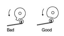
■Driving Mechanism
Use of a driving mechanism which will cause physical impact to the actuator should be avoided.
|
Technical Notes on Electrical Characteristics
-
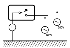
1. The snap-action switch is designed for AC operations. While it has small contact gaps and no arc absorber, it may be used for low-capacity DC operations.
Please refer to the rating of each product - 2. For applications with very small switching voltage or current, choose the low-level load type (Au contact).
|
- 3. When selecting a contact type of a snap-action switch to be used for low-level load switching, the following should be noted. Silver contacts’ surfaces are prone to be oxidized and form a sulfide film. The switch operates with no problems at the beginning of use. However, as the contact surfaces develop films with time, the film may not be broken by the switching operation, causing a conduction failure. Therefore, please choose the Au contact type for switching a load of 0.1 A or below.
- 4. Application to Electronic Circuits
- ・The snap-action switch contacts can sustain bounce or chatter when closed. Bounce or chatter can cause noise or pulse count errors when the snap action switch is used in electronic circuits.
- ・If contact bounce or chatter poses problems in the vicinity of the OP and RP, use a suitable absorption network, such as a C/R network.
- 5. Check the surge current, normal current and surge duration.
- 6. Contact resistance given in performance specifications is measured with a voltage drop method using 6 to 8 V DC, 1 A (except for low-level load type). Contact resistance across COM and N.C. terminals is measured in the open position, while contact resistance across COM and N.O. terminals is measured in the closed position.
- 7. To prevent contact welding failure, be sure to use a serial resistance for each capacitive load.
- 8. If snap-action switch operation is synchronized with the AC supply phase, this may cause: shortened electrical life, contact fusion failure, contact transfer, or other reliability problems.
Cautions in a Circuit
- 1.Contact protection is recommended when snap-action switches are used in an inductive load circuit.
| Circuit diagram | Cautions for use | ||
|---|---|---|---|
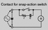 |
(1) r = more than 10 Ω (2) In an AC circuit
|
||
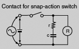 |
Can be used for both AC and DC. Impedance of r is nearly equal to impedance of R. C: 0.1 μF |
||
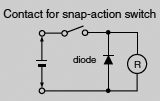 |
(1) For DC circuits only. | ||
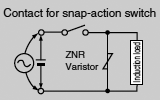 |
Can be used for both AC and DC. |
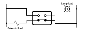
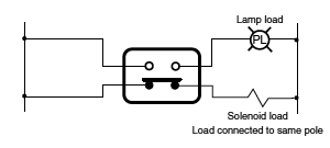
- 2.Do not connect the contacts on individual switches to different type or different poles of the power supply.
|
|
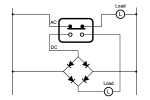
- 3.Avoid circuits which apply voltage between contacts. (This may lead to mixed deposition.)
|
Mounting State and Environment
■Checking the insulation distance
After mounting and wiring, check the insulation distance between terminals and the ground. If the insulation distance is inadequate, mount insulating material between as required.
■Fastening the snap-action switch body
See the Section “Cautions for Use” for the individual switch.
■Position adjustment with effector
- 1. The effector should be positioned so that direct force is not applied to the pushbutton or actuator in its free position. The operating force to the pushbutton should only be applied in a perpendicular direction.
- 2. Note that the use of the switch as a stopper may cause an operational problem.
■Switch installation position
-
Basically, the switch should be installed so that the object to press the switch’s plunger or lever can press it down to 70 to 100% of OT of the switch.
When determining the position, the tolerance of OP (Operating Position) and other factors should be taken into account.
The following describes the case where the strictest tolerance conditions are adopted. - Example: Hinge lever type FS switch
| Reference values | : | OP=8.8±0.8mm |
|---|---|---|
| : | PT=max.2.8mm | |
| : | OT=min.1.2mm |
|
| 1. | When the switch is not pressed |
|
The object to press the lever should not be in contact with the lever. For this purpose, the object should be at a distance from the switch father than the maximum FP (Free Position) value. FP max = OP max + PT max = 9.6 + 2.8 = 12.4 mm max The object should be at a distance of 12.4 mm or more from the mounting hole. |
|
| 2. | Depressed position |
|
The plunger/lever should be pressed down to 70% or more of OT (Over Travel).
Therefore, the depressed position should be calculated based on the minimum value of
OP (Operating Position) and the 70 and 100% of the OT value. OP min - 70% of OT = 8.0 - 0.84 = 7.16 mm OP min - 100% of OT = 8.0 - 1.2 = 6.80 mm The plunger/lever should be pressed down to the position of 6.80 to 7.16 mm from the mounting hole. |
■Soldering precautions
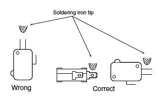
- For manual soldering, lay the terminals flat (horizontal with the ground) and quickly perform the soldering operation using a soldering iron with the appropriate heat capacity and the proper amount of solder.
Take care that the flux does not flow into the switch interior by using a ventilation fan to discharge flux gas and to prevent contact of the switch body with the soldering iron tip.
Be careful not to apply force to the lead wires or the terminal portions immediately after soldering.
The temperature setting and time conditions vary depending on the product.
See the Section “Cautions for Use” for each product.
|
■Avoid using in a silicon atmosphere*
Avoid using organic silicon rubber, adhesives, sealing compounds, oil, grease, and wires in a silicon atmosphere.
■Please consult us when using under the following conditions*
- 1.Environments where hydrogen sulfide or other corrosive gases are present.
- 2.Environments where gasoline, thinner or other flammable, explosive gases are present.
- 3. Dusty environments (for non-seal type snap action switches).
- 4.The perpendicular operating speed exceeds the allowable operating speed.
- 5.Switching between different poles.
- 6.Use in environments not in the prescribed temperature or humidity range.
| * | Select contact sulfurization (clipping) prevention products (FS and Au-clad double layer contacts) for use with extremely small loads or an environmentresistant Turquoise switch. |
|---|
■Storage precautions
To prevent discoloration due to sulfurization of the terminals (silver-plated), store the switches in a polyethylene bag or other suitable airtight container.
■Usage, storage, and transport conditions (except turquoise switches)
During usage, storage, or transportation, avoid locations subject to direct sunlight and maintain normal temperature, humidity, and pressure conditions.
The allowable specifications for environments suitable for usage, storage, and transportation are given below.
- 1.Temperature: The allowable temperature range differs for each switch, so refer to the switch's individual specifications. In addition, when transporting or storing switches while they are tube packaged, there are cases when the temperature may differ from the allowable range. In this situation, be sure to consult the individual specifications.
- 2.Humidity: The allowable temperature range differs for each switch, so refer to the switch's individual specifications.
- 3.Pressure: 86 to 106 kPa
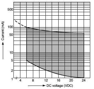
The humidity range varies with the temperature. Use within the range indicated in the graph below.
|
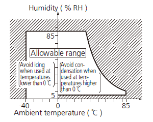
(The allowable temperature depends on the switch.)
-
Condensation will occur inside the switch if there is a sudden change in ambient temperature when used in an atmosphere
of high temperature and high humidity.
This is particularly likely to happen when being transported by ship, so please be careful of the atmosphere when shipping.
Condensation is the phenomenon whereby steam condenses to cause water droplets that adhere to the switch when an atmosphere
of high temperature and humidity rapidly changes from a high to low temperature or when the switch is quickly moved from a low
humidity location to one of high temperature and humidity.
Please be careful because condensation can cause adverse conditions such as deterioration of insulation, coil cutoff, and rust. - Condensation or other moisture may freeze on the switch when the temperatures is lower than 0°C. This causes problems such as sticking of movable parts or operational time lags.
- The plastic becomes brittle if the switch is exposed to a low temperature, low humidity environment for long periods of time.
- Storage for extended periods of time (including transportation periods) at high temperatures or high humidity levels or in atmospheres with organic gases or sulfide gases may cause a sulfide film or oxide film to form on the surfaces of the contacts and/or it may interfere with the functions. Check out the atmosphere in which the units are to be stored and transported.
- In terms of the packing format used, make every effort to keep the effects of moisture, organic gases and sulfide gases to the absolute minimum.
■We reserve the right to modify without notice the materials, internal components, and other parts to improve product quality.
■Handling precautions
When handling the switches, be careful not to drop them on the floor since this may damage them.
■Others
- 1. Failure modes of switches include short-circuiting, open-circuiting and temperature rises. If this switch is to be used in equipment where safety is a prime consideration, examine the possible effects of these failures on the equipment concerned, and ensure safety by providing protection circuits or protection devices. In terms of the systems involved, make provision for redundancy in the design and take steps to achieve safety design.
- 2. The ambient operating temperature (and humidity) range quoted is the range in which the switch can be operated on a continuous basis: it does not mean that using the switch within the rating guarantees the durability performance and environment withstanding performance of the switch. For details on the performance guarantee, check the specifications of each product concerned.
Types of Actuators
| Shape | Classification | Pretravel (PT) | Overtravel (OT) | Operating Force (OF) | Vibration Shock |
Features | |
|---|---|---|---|---|---|---|---|
 |
Pin plunger | Small | Small | Large | Out-standing | Appropriate for linear short-stroke action. Pin plunger acts directly on snap action mechanism, enabling high-precision positioning. Amount of movement after operation is smallest among all of the actuators, however, so reliable stopper is required. | |
 |
Hinge lever | Large | Medium | Small | Possible |
Little force required for operation. Appropriate for use with low-speed cams and dogs; has large stroke. Lever available in various shapes to fit operating unit. |
|
 |
Simulated roller lever |
Large | Medium | Small | Possible | Tip of hinge lever is bent into a semi-circle, enabling use as a simple roller type. | |
 |
Leaf lever | Large | Large | Small | Excellent | Play in lever is used to assure maximum stroke. Construction provides for space where lever is attached, for outstanding resistance to freezing. | |
 |
Hinge roller lever | Large | Medium | Small | Possible |
This is a hinge lever with a roller, and can be used with high-speed cams and dogs. The force required for pin plunger action is lighter than that of the lever, and the stroke is longer. |
|
Catalog Download
|
|
Title | Language | File size | Update |
|---|---|---|---|---|
| マイクロスイッチ・転倒検知スイッチ用語説明と使用上の注意事項(共通) マイクロスイッチ・転倒検知スイッチ(共通) |
JP | 270.0KB | January 9, 2024 | |
| Technical Terminology & Cautions for Use (Detection Switches) Detection Switches |
EN | 117.3KB | January 9, 2024 | |
| 术语说明和使用注意事项 微动开关·翻转检测开关·门互锁开关使用注意事项(共通) |
CN-Simplified | 846.5KB | January 26, 2024 |
BY EMAIL
- U.S.A.
- +1-800-344-2112
- Europe
- +49-89-45354-1000
- China
- +86-10-59255988
- Singapore
- +65-6299-9181


Seal Type Switches
-
ABJ (BJ) Turquoise Switches Ultra-miniature Size Sealed Switches -
ABS (BS) Turquoise Switches Subminiature Size Sealed Switches -
ABV (BV) Turquoise Switches Miniature Size Sealed Switches -
Turquoise Stroke Switches Long Stroke and Sliding Contact Construction Sealed Switches -
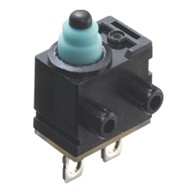
Turquoise Stroke Mini Switches Small size and Long Stroke Sliding Contact Construction Sealed Switches -
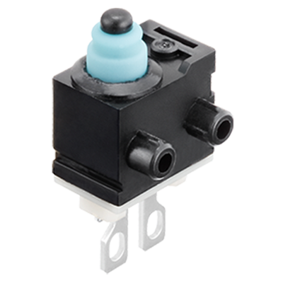
Turquoise Stroke Mini Switch Resistor installed type Small seal switches with wiring failure detecting function
Requests to customers (Automation Control Components & Industrial Device) [Excluding specific product]
Requests to customers (Automation Control Components & Industrial Device) [For specific product]
Requests to customers (FA Sensors & Components [Excluding motors])
Requests to customers (Dedicated to industrial motors)
- COMPONENTS & DEVICES
- FA SENSORS & COMPONENTS
- Fiber Sensors
- Photoelectric Sensors / Laser Sensors
- Micro Photoelectric Sensors
- Light Curtains / Safety Components
- Area Sensors
- Inductive Proximity Sensors
- Particular Use Sensors
- Sensor Options
- Wire-Saving Systems
- Programmable Controllers / Interface Terminal
- Human Machine Interface
- Pressure Sensors / Flow Sensors
- Measurement Sensors
- Static Control Devices
- Laser Markers / 2D Code Readers
- Machine Vision System
- Energy Management Solutions
- Timers / Counters / FA Components
- MOTORS
![]()