[System Maintenance Notice]
Due to ongoing system maintenance, the site search and specification search functions are temporarily unavailable. We apologize for any inconvenience this may cause and appreciate your understanding.
【Notification of Manufacturer Change for Panasonic Industrial Devices SUNX Products and Panasonic Industrial Devices SUNX Tatsuno Products】
From April 1, 2024, the terms "Panasonic Industrial Devices SUNX Co., Ltd." and "Panasonic Industrial Devices SUNX Tatsuno Co., Ltd."
in this page and in the manuals and other documents to be downloaded will all be replaced with "Panasonic Industry Co., Ltd." and applied accordingly.

 Business
> Industrial Devices
> Automation Controls Top
> FA Sensors & Components
> Timers / Counters / FA Componets
> Counters
> LC2H Total Counter(Discontinued Products)
> Cautions For Use
Business
> Industrial Devices
> Automation Controls Top
> FA Sensors & Components
> Timers / Counters / FA Componets
> Counters
> LC2H Total Counter(Discontinued Products)
> Cautions For Use
LC2H Total Counter (Discontinued Products)
|
We are sorry, the products have been discontinued. Please refer to the details of the discontinued products and the recommended substitutes list below.
|
Cautions For Use
Protective circuit for timer contact
In the circuit that switches an inductive load, a contact failure may occur at a contact point due to surge or inrush current resulting from that switching. Therefore, it is recommended that the following protective circuit be used to protect the contact point.
| CR circuit (r: resistor c: capacitor) | |||
|---|---|---|---|
| Circuit |  |
 |
|
| Application | AC | * Note: | Available |
| DC | Available | Available | |
| Features/Others | If the load is a relay or solenoid, the release time lengthens. Effective when connected to both contacts if the power supply voltage is 24 or 48 V and the voltage across the load is 100 to 200 V. | ||
| If the load is a timer, leakage current flows through the CR circuit causing faulty operation. Note: If used with AC voltage, be sure the impedance of the load is sufficiently smaller than that of the CR circuit. |
- | ||
| Device Selection | As a guide in selecting r and c, c: 0.5 to 1 µF per 1 A contact current r: 0.5 to 1 ohm per 1 V contact voltage Values vary depending on the properties of the load and variations in timer characteristics. Capacitor c acts to suppress the discharge the moment the contacts open. Resistor r acts to limit the current when the power is turned on the next time. Test to confirm. Use a capacitor with a breakdown voltage of 200 to 300 V. Use AC type capacitors (non-polarized) for AC circuits. |
||
| Diode circuit | Varistor circuit | ||
|---|---|---|---|
| Circuit |  |
 |
|
| Application | AC | Not Available | Available |
| DC | Available | Available | |
| Features/Others | The diode connected in parallel causes the energy stored in the coil to flow to the coil in the form of current and dissipates it as joule heat at the resistance component of the inductive load. This circuit further delays the release time compared to the CR circuit. (2 to 5 times the release time listed in the catalog) |
Using the rated voltage characteristics of the varistor, this circuit prevents excessively high voltages from being applied across the contacts. This circuit also slightly delays the release time. Effective when connected to both contacts if the power supply voltage is 24 or 48 V and the voltage across the load is 100 to 200 V. |
|
| Device Selection | Use a diode with a reverse breakdown voltage at least 10 times the circuit voltage and a forward current at least as large as the load current. In electronic circuits where the circuit voltages reverse breakdown voltage of about 2 to 3 times the power supply voltage. |
- | |
Type of Load and Inrush Current
The type of load and its inrush current characteristics, together with the switching frequency are important factors which cause contact welding. Particularly for loads with inrush currents, measure the steady state current and inrush current and use a relay or magnet switch which provides an ample margin of safety. The table below shows the relationship between typical loads and their inrush currents.
| Type of load | Inrush current |
|---|---|
| Resistive load | Steady state current |
| Solenoid load | 10 to 20 times the steady state current |
| Motor load | 5 to 10 times the steady state current |
| Incandescent lamp load | 10 to 15 times the steady state current |
| Mercury lamp load | 1 to 3 times the steady state current |
| Sodium vapor lamp load | 1 to 3 times the steady state current |
| Capacitive load | 20 to 40 times the steady state current |
| Transformer load | 5 to 15 times the steady state current |
When you want large load and long life of the counter, do not control the load direct with a timer. When the timer is designed to use a relay or a magnet switch, you can acquire the longer life of the counter.
Connection of input (Except for LC4H-S/AC type)
Since LC4H series counters use a transformerless power supply system, the input equipments must have the power supply transformer in which the secondary side is not grounded with the primary and secondary sides insulated, in order to prevent interference of the power supply circuit when connecting the external input circuit as Fig. A.
Be sure not to use an autotransformer. In case of secondary side grounded or using the autotransformer, this product may be destroyed due to short circuit electrically as Fig. B (1 and 2).
In case of F.G. terminal of equipments such a PLC grounded in secondary side of the transformer, inner circuits of this product and the input equipment may be destroyed due to short circuit electrically as Fig.B (3).
Therefore, use the isolated type counters or do not ground F.G. terminal of the products.
|
Long Continuous Current Flow
Avoid keeping the counter on for a long period of time (over one month). Otherwise heat is generated and accumulated inside the counter, which may deteriorate its electronic parts. If the counter must be kept on for a long period of time, a relay is added. See the circuit diagram below.
|
Leakage current
- 1.For connecting and disconnecting operating voltage to the counter, a circuit should be used, which will prevent the flow of leakage current. For example, a circuit for contact protection as shown in Fig A. will permit leakage current flow through R and C, causing erroneous operation of the counter. Instead, the circuit shown in Fig. B should be used.
|
- 2.If the counter is directly switched with a non-contact element, leak current may flow into the counter and cause it to malfunction.
Pin connections
Correctly connect the pins while seeing the pin layout/connection diagram. In particular, the DC type, which has polarities, does not operate with the polarities connected reverse. Any incorrect connection can cause abnormal heating or ignition.
Connection to operation power supply
- 1.Apply the entire supply voltage through a switch, relay or other contact.
- 2.The operation voltage for the DC type must be at the specified ripple percentage or less. The average voltage must fall within the allowable operation voltage range.
| Rectification type | Ripple percentage |
|---|---|
| Single-phase, full-wave | Approx. 48% |
| Three-phase, full-wave | Approx. 4% |
| Three-phase, half-wave | Approx. 17% |
- 3.Make sure that no induced voltage and residual voltage are applied between the power pins on the timer after the power switch is turned OFF.
(If the power line is wired in parallel with the high-voltage and motor lines, induced voltage may be produced between the power pins.)
Control output
- 1.Keep the load capacity below the counter's rated control capacity. If used above the rating, the counter's service life may shorten. With the transistor output type counters, transistors may be damaged.
Installing the counter
- 1.To install the counter, use the dedicated pin bracket or socket (cap). Avoid connecting the pins on the counter by directly soldering them.
- 2.In order to maintain the characteristics, do not remove the counter cover (case).
Superimposed surge of power supply
For the superimposed surge of power supply, the standard waveform (±1.2×50μs or ±1×40μs) is taken as the standard value for surge-proof voltage.
(The positive and negative voltages are applied each three or five times between the power pins.)
For the standard values for the LC4H type counters, see the respective items in "Caution on usage."
|
If external surge occurs exceeding the specified value, the internal circuit may break down. In this case, use a surge absorption element. The typical surge absorption elements include a varistor, a capacitor, and a diode. If a surge absorption element is used, use an oscilloscope to see whether or not the foreign surge exceeding the specified value appears.
Signal input
The counter's signal input comes in two ways. One is by opening and closing the input terminal. The other is by applying a specified H-level or L-level voltage to the input terminal.
For an input sensor's residual voltage, input impedance, input voltage level and other signal input conditions, see the ratings for each type of product.
Operating environment
- 1.For the ambient operating temperature and humidity, see the ratings for each type of product.
- 2.Avoid using the counter in a location where (a) inflammable or corrosive gas is generated, (b) the counter is exposed to much dust and other foreign matter; (c) water or oil is splashed on the counter; or (d) vibrations or shocks are given to the counter.
- 3.The counter cover (case), the knobs, and the dials are made of polycarbonated resin. Therefore, prevent the counter from being exposed to organic solvents such as methyl alcohol, benzine, and thinner, strong acid substances such as caustic soda, and ammonia and avoid using the counter in atmosphere containing any of those substances.
- 4.If the counter is used where noises are emitted frequently, separate the input signal elements (such as a sensor), the wiring for the input signal line, and the counter as far as possible from the noise source and the high power line containing noises.
|
Checking the actual load
In order to increase the reliability in the actual use, check the quality of the counter in the actual usage.
Others
- 1. If the counter is used exceeding the ratings (operation voltage and control capacity), the contact life, or any other specified limit, abnormal heat, smoke, or ignition may occur.
- 2.The LC2H series counter, which provides a power failure compensation capability, incorporates a lithium battery.
Never disassemble the lithium battery or throw it into fire because this may affect humans and facilities. The lithium battery must be disposed of as an incombustible like other used batteries. - 3.If any malfunction of the counter is likely to affect human life and properties, give allowance to the rated values and performance values. In addition, take appropriate safety measures such as a duplex circuit from the viewpoint of product liabilities.
Precautions in Using The LC2H Series
Insulation sheet
Before using a panel mounting type, please pull and remove the insulation sheet from the side of the product in the direction of the arrow. In consideration that the product might be stored for long periods without being used, an insulation sheet is inserted before shipping. Remove the insulation sheet and press the front reset button.
|
|
Waterproof construction
LC2H total counter (installation frame type)
The operation part of the panel installation type (installation frame type) is constructed to prevent water from entering the unit and a rubber gasket is provided to prevent water from entering the gap between the unit and the panel cutout. There must be sufficient pressure applied to the rubber gasket to prevent water from entering. Be sure to use the mounting reinforcement screws when installing the mounting frame (ATH3803).
| Note: | The one-touch installation type is not waterproof. |
|---|
|
LC2H preset counter
- 1.The front plate will not be waterproof when this product is installed on a panel.
|
When installing the mounting frame and rubber gasket please remove the pre-attached o-ring
- 2.Panel installation order
- 1.Remove o-ring.
- 2.Place rubber gasket.
- 3.Insert counter into panel.
- 4.Insert mounting frame from the rear.
- 5.Secure with mounting screws (two locations)
Do not use in the following environments
- 1.In places where the temperature changes drastically.
- 2.In places where humidity is high and there is the possibility of dew.
(When dew forms the display may vanish and other display errors may occur.)
Conditions of use
- 1.Do not use on places where there is flammable or corrosive gas, lots of dust, presence of oil, or where the unit might be subject to strong vibrations or shocks.
- 2.Since the cover is made of polycarbonate resin, do not use in places where the unit might come into contact with or be exposed to environments that contain organic solvents such as methyl alcohol, benzene and thinner, or strong alkali substances such as ammonia and caustic soda.
Cautions regarding battery replacement
- 1.Remove wiring before replacing the battery. You may be electrocuted if you come into contact to a part where high voltage is applied.
- 2.Make sure you are not carrying a static electric charge when replacing the battery.
- 3.Battery replacement procedure
1.For LC2H total counter (one-touch installation type)
- 1.Remove the up/down hook of the case using a tool.
- 2.Pull the unit away from the case.
- 3.Remove the battery from the side of the unit. Do not touch the display or other parts.
- 4.Before inserting wipe clean the surface of the new battery.
- 5.Insert the new battery with the "+" and "–" sides in the proper position.
- 6.After replacing the battery, return the unit to the case. Verify that the hook of the case has properly engaged.
- 7.Before using, press the reset button on the front.
|
2.For LC2H total counter (installation frame type)
- 1.Remove the battery cover from the case.
- 2.Remove the battery from the side of the case. The battery will come loose if you put the battery side face down and lightly shake the unit.
- 3.Before inserting wipe clean the surface of the new battery.
- 4.Insert the new battery with the "+" and "–" sides in the proper position.
- 5.After replacing the battery, return the battery cover to the case. Verify that the hook of the battery cover is properly engaged.
- 6.Before using press the reset button on the front.
|
Terminal connection
Tighten the terminal screws with a torque of 0.8 N·cm or less.
LC2H Total Counter
Non-voltage input type
Common to both the panel mounting type, and the PC board mounting type
| 1: | Never apply voltage to the non-voltage input type. This will damage the internal elements. Also, since there is a possibility of erroneous operation, do not connect in parallel the inputs of a non-voltage input type and another counter from a single input signal. |
|---|---|
| 2: | Since the current flow is very small from the count input and reset input terminals ( and on the panel mounting type and terminals (15) to (17) and (26) to (28) on the PC board mounting type) please use relays and switches with high contact reliability. |
| 3: | When inputting with an open collector of a transistor, use a transistor for small signals in which ICBO is 1 μA or less and always input with no voltage. |
| 4: | When wiring, try to keep all the input lines to the count and reset inputs as short as possible and avoid running them together with high voltage and power transmission lines or in a power conduit. Also, malfunctions might occur if the floating capacitance of these wires exceeds 500 pF (10 m 32.808 ft for parallel wires of 2 mm2 0.003 in2). When using 2 kHz mode, use with a wiring floating capacitance of 120 pF (3 m 9.843 ft for parallel wires of 2 mm2 0.003 in2). In particular, when using shielded wiring, be careful of the capacitance between wires. |
PC board mounting type
| 1: | For external power supply use manganese dioxide or lithium batteries (CR type: 3V). |
|---|---|
| 2: | Always reset after external power is applied and confirm that the display reads "0". |
| 3: | Make the wiring from the battery to the counter unit as short as absolutely possible. Also, be careful of polarity. |
| 4: | Calculate battery life with the following formula. t = A / I t: battery life [h] I: LC2H current consumption [mA] A: battery capacity until minimum operation voltage is reached [mAh] |
| 5: | Hand solder to the lead terminal. Do not dip solder. With the tip of the soldering iron at 300 ℃ 572 ℉ perform soldering within 3 seconds (for 30 to 60 W soldering iron). |
Voltage input type
| 1: | Be aware that applying more than 30 V DC to count input terminals (1) and (2), and reset input terminals (3) and (4) will cause damage to the internal elements. |
|---|---|
| 2: | For external resetting use H level (application of 4.5 to 30 V DC) between reset terminals (3) and (4) of the rear terminals. In this case, connect (+) to terminal 3 and (-) to terminal (4). This is the valid polarity; therefore, the counter will not work if reversed. |
| 3: | When wiring, try to keep all the input lines to the count and reset inputs as short as possible and avoid running them together with high voltage and power transmission lines or in a power conduit. Also, malfunctions might occur if the floating capacitance of these wires exceeds 500 pF (10 m 32.808 ft for parallel wires of 2 mm2 0.003 in2). |
Free voltage input type
| 1: | Use count input terminals (1) and (2) for free voltage input and reset terminals (3) and (4) for non-voltage input. |
|---|---|
| 2: | Be aware that the application of voltage that exceeds the voltage range of the H level to the count input terminal, and the application of voltage to the reset input terminal, can cause damage to the internal elements. |
| 3: | Since the current flow is very small from reset input terminal (3), please use relays and switches with high contact reliability. |
| 4: | When inputting a reset with an open collector of a transistor, use a transistor for small signals in which ICBO is 1 μA or less and always input with no voltage. |
| 5: | To reset externally, short reset input terminals (3) and (4) on the rear. |
| 6: | Input uses a high impedance circuit; therefore, erroneous operation may occur if the influence of induction voltage is present. If you plan to use wiring for the input signal that is 10 m 32.808 ft or longer (wire capacitance 120 pF/m at normal temperature), we recommend the use of a CR filter or the connection of a bleeder resistor |
How to reset multiple panel mounting type counters all at once (input is the same for count)
1.Non-voltage input type
|
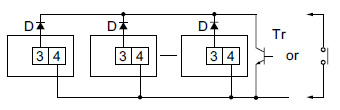
| Notes) | 1. Use the following as a guide for choosing transistors used for input (Tr). Leakage current < 1 μA |
|---|---|
| 2. Use as small a diode (D) as possible in the forward voltage so that the voltage between terminals 3 and 4 during reset input meets the standard value (0.5 V). ( At IF = 20 μA, forward voltage 0.1 and higher.) |
2.Voltage input type
|
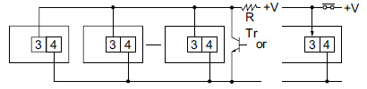
| Note) | Make sure that H (reset ON) level is at least 4.5V. |
|---|
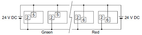
Backlight luminance
To prevent varying luminance among backlights when using multiple backlight types, please use the same backlight power supply.
|
Environment for use
- 1.Ambient conditions
- Overvoltage category II, pollution level 2
- ndoor use
- Acceptable temperature and humidity range: --10 to +55°C, 35 to 85%RH (with no condensation at 20°C)
- Under 2000 m elevation
- 2.Use the main unit in a location that matches the following conditions.
- There is minimal dust and no corrosive gas.
- There is no combustible or explosive gas.
- There is no mechanical vibration or impacts.
- There is no exposure to direct sunlight.
- Located away from large-volume electromagnetic switches and power lines with large electrical currents.
- 3.Connect a breaker that conforms to EN60947-1 or EN60947-3 to the voltage input section.
- 4.Applied voltage should be protected with an overcurrent protection device (example: T 1A, 250 V AC time lag fuse) that conforms to the EN/IEC standards. (Free voltage input type)
BY EMAIL
- U.S.A.
- +1-800-344-2112
- Europe
- +49-89-45354-1000
- China
- +86-10-59255988
- Singapore
- +65-6299-9181


Requests to customers (Automation Control Components & Industrial Device) [Excluding specific product]
Requests to customers (Automation Control Components & Industrial Device) [For specific product]
Requests to customers (FA Sensors & Components [Excluding motors])
Requests to customers (Dedicated to industrial motors)
- COMPONENTS & DEVICES
- FA SENSORS & COMPONENTS
- Fiber Sensors
- Photoelectric Sensors / Laser Sensors
- Micro Photoelectric Sensors
- Light Curtains / Safety Components
- Area Sensors
- Inductive Proximity Sensors
- Particular Use Sensors
- Sensor Options
- Wire-Saving Systems
- Programmable Controllers / Interface Terminal
- Human Machine Interface
- Pressure Sensors / Flow Sensors
- Measurement Sensors
- Static Control Devices
- Laser Markers / 2D Code Readers
- Machine Vision System
- Energy Management Solutions
- Timers / Counters / FA Components
- MOTORS
![]()