[System Maintenance Notice]
Due to ongoing system maintenance, the site search and specification search functions are temporarily unavailable. We apologize for any inconvenience this may cause and appreciate your understanding.
【Notification of Manufacturer Change for Panasonic Industrial Devices SUNX Products and Panasonic Industrial Devices SUNX Tatsuno Products】
From April 1, 2024, the terms "Panasonic Industrial Devices SUNX Co., Ltd." and "Panasonic Industrial Devices SUNX Tatsuno Co., Ltd."
in this page and in the manuals and other documents to be downloaded will all be replaced with "Panasonic Industry Co., Ltd." and applied accordingly.

 Business
> Industrial Devices
> Automation Controls Top
> FA Sensors & Components
> Programmable Controllers / Interface Terminal
> Programmable Controllers / Interface Terminal
> FP7
> Specifications
Business
> Industrial Devices
> Automation Controls Top
> FA Sensors & Components
> Programmable Controllers / Interface Terminal
> Programmable Controllers / Interface Terminal
> FP7
> Specifications
FP7
|
Partly Order Discontinued
|
|||||
Specifications
- CPU units
- Expansion units
- Add-on cassettes (communication cassettes)
- Add-on cassettes (function cassettes)
- Digital input and output units
- Analog input and output units
- Temperature input units
- Multi input/output unit
- High-speed Counter Units
- Motion control units
- Positioning units
- Pulse Output Units
- Power supply units
- Serial Communication Unit
- Multi-wire link unit
- PHLS (remote I/O) units
- General specifications on each units
- Discontinued products
CPU units
Control specifications
| Item | AFP7CPS4RE(S) (Note 6) | |||||
|---|---|---|---|---|---|---|
| Memory capacity |
Memory selection pattern (Note 1) |
1 | 2 | 3(Factory default) | 4 | 5 |
| Program (steps) (Note 2) | 234,000 | 221,500 | 196,000 | 144,500 | 51,500 | |
| Data register (words) (Note 2) |
65,536 | 131,072 | 262,144 | 524,288 | 999,424 | |
| Number of max. program block (PB) |
468 | 443 | 392 | 289 | 103 | |
| Item | AFP7CPS3RE(S)/AFP7CPS3R(S) (Note 6) | ||||
|---|---|---|---|---|---|
| Memory capacity |
Memory selection pattern (Note 1) |
1(Factory default) | 2 | 3 | 4 |
| Program (steps) (Note 2) | 121,500 | 96,000 | 64,000 | 32,000 | |
| Data register (words) (Note 2) |
131,072 | 262,144 | 425,984 | 589,824 | |
| Number of max. program block (PB) |
243 | 192 | 128 | 64 | |
| Item | AFP7CPS2R | ||
|---|---|---|---|
| Memory capacity |
Memory selection pattern (Note 1) |
1(Factory default) | 2 |
| Program (steps) (Note 2) | 64,000 | 32,000 | |
| Data register (words) (Note 2) |
131,072 | 262,144 | |
| Number of max. program block (PB) |
128 | 64 | |
| Item | AFP7CPS4RE(S) / AFP7CPS3RE(S) / AFP7CPS3R(S) / AFP7CPS2R |
|---|---|
| Programming method | Relay symbol method |
| Control method | Cyclic operation method |
| Program memory | Built-in flash ROM (no backup battery required) |
| Operation speed | Basic instruction: Min. 11 ns/step (AFP7CPS2R: 14 ns/step) |
| External input (X) / output (Y) | 8,192 points (Note 4) / 8,192 points (Note 4) |
| Internal relays (R) | 32,768 points |
| System relays (SR) | Indicate operation status of various relays is shown. |
| Link relays (L) | 16,384 points |
| Timers (T) | 4,096 points: Timer capable of counting (units: 10 μs, 1 ms, 10 ms, 100 ms or 1 sec.) × 4,294,967,295 |
| Counters (C) | 1,024 points, Counter capable of counting 1 to 4,294,967,295 |
| Link data registers (LD) | 16,384 words |
| System data registers (SD) | Internal operation status of various registers is shown. |
| Index registers (I0 to IE) | 15 long words / With switching function |
| Master control relay (MCR) | Unlimited |
| Number of labels (LOOP) | Max. 65,535 points for each program block (PB) |
| Differential points | Unlimited |
| Number of step ladders | Unlimited |
| Number of subroutines | Max. 65,535 points for each program block (PB) |
| Number of interrupt programs | 1 periodical interrupt program |
| SD memory card function | SDHC memory cards of up to 32 GB are usable. *except for AFP7CPS2R |
| Constant scan | Available (0 to 125 ms) |
| Clock / calendar (Note 3) |
Year (last two digits), month, day, hours (24-hour display) minutes, seconds, day of week |
| Battery life | 3.3 years or more (at +25 ℃ +77 ℉) (when no power is supplied) *except for AFP7CPS2R |
| Security function (Note 5) |
Password / Restricted distribution / Read disable setting / Encryption |
| PLC link function (Serial communication / MEWNET-W0) |
Max. 16 units, link relays: 1,024 points, link registers: 128 words. (Data transfer and remote programming are not supported) (Link area allocation is switchable between the first and the second half) |
Notes :
| 1) | The factory default setting is pattern 3 for AFP7CPS4RE(S) and pattern 1 for AFP7CPS3RE(S), AFP7CPS3R(S) and AFP7CPS2R. |
|---|---|
| 2) | For data register (DT), data up to 262,144 words can be backed up. |
| 3) | Precision of calendar; At 0 ℃ +32 ℉, 95 sec. or less error per month, at +25 ℃ +77 ℉, 15 sec. or less error per month, at +55 ℃ +131 ℉, 130 sec. or less error per month |
| 4) | Hardware configuration governs the actually usable number of I/O points. When I/O points are not actually used, usable as internal relays. |
| 5) | Encryption can be used for AFP7CPS4RES, AFP7CPS3RES and AFP7CPS3RS. |
| 6) | Products with an "S" at the end of a part number have the encryption function. |
COM port communication specifications
| Item | Specifications |
|---|---|
| Interface | RS-232C, three-wire system, 1 channel (Note 1) |
| Transmission distance | 15 m 49.213 ft |
| Transmission speed | 300, 600, 1200, 2400, 4800, 9600, 19200, 38400, 57600, 115200, 230400 bits/sec. |
| Communication method | Half-duplex system |
| Synchronous method | Start-stop synchronization system |
| Transmission format | Stop bit: 1 bit / 2 bits |
| Parity: none / odd / even | |
| Data length: 7 bits / 8 bits | |
| Start code: with STX / without STX | |
| End code: CR / CR + LF / none / ETX | |
| Data transmission order | Transmit from bit 0 in character units. |
| Communication mode | General-purpose communication, Computer link and MODBUS-RTU |
Note: 1) SD, RD and SG terminals are isolated from internal circuits.
Dedicated power supply output port specifications for GT series programmable display
| Output terminal (Note 1) | Connecting Programmable Display model |
|---|---|
| 5 V | For 5 V DC type GT series Programmable Display |
| 24 V (Note 2) | For 24 V DC type GT series Programmable Display |
Notes:
| 1) | 5 V and 24 V DC types are not usable at the same time. |
|---|---|
| 2) | Use 21.6 to 26.4 V DC to power the CPU unit. Please check the “GT Series Manual” for grounding of the GT series programmable display. The AFP7CPS2R is not provided with this port. |
LAN port communication specifications [without AFP7CPS3R(S) and AFP7CPS2R]
| Item | Specifications |
|---|---|
| Communication interface | Ethernet 100BASE-TX / 10BASE-T |
| Baud rate | 100 Mbps, 10 Mbps auto negotiation function |
| Total cable length | 100 m 328 ft (500 m 1,640 ft when a repeater is used) |
| Number of nodes | 254 units |
| Number of simultaneous connections | Max. 220 connections (user connection: 216, system connection: 4) |
| Communication protocol (Communication layer) |
TCP / IP, UDP |
| DNS | Supports name servers |
| DHCP / DHCPV6 | Automatic IP address acquisition |
| FTP server / Client (SSL/TLS compatible) | Server function: file transfer, number of user: 3 Client function: data and file transfer |
| HTTP server / Client (SSL/TLS compatible) | Server function: system web, Customer web (8 MB), number of concurrent session: 16 Client function: data transfer |
| SMTP client (SSL/TLS compatible) | Client function: mail transfer |
| SNTP | Time adjustment function |
| General-purpose communication | 16 kB / 1 connection (user connection: 1 to 16) |
| Dedicated communication | EtherNet/IP MEWTOCOL-COM (master/slave) MEWTOCOL7-COM (slave) MODBUS-TCP (master/slave) MEWTOCOL-DAT (master/slave) MC protocol (Note) (master/slave) |
Note: MC protocol is a short form denoting MELSEC communication protocol; MELSEC is a registered trademark of Mitsubishi Electric Corporation. QnA compatible 3E frame, only binary (bulk writing and bulk reading) use is available.
Web server specifications
| Item | Specifications |
|---|---|
| Compatible CPU unit | Ver. 3.30 or later CPU unit with built-in Ethernet function |
| Web server | Number of simultaneous accesses: 16 sessions System Web: system monitor function Custom Web: 13.83 MB max. content capacity |
| Control Web Creator compatible OS |
Windows® 10 (32bit 64bit) / Windows® 11 |
| Web server accessible browsers |
[Windows®] Google Chrome、Mozilla Firefox、Opera、Microsoft Edge [macOS] Safari、Google Chrome、Mozilla Firefox [iOS] Safari、Google Chrome [Android] Google Chrome |
Notes:
| 1) | Windows and Microsoft Edge are registered trademarks or trademarks of Microsoft Corporation in the United States and other countries. Google Chrome and Android are registered trademarks of Google Inc. Safari, macOS and iOS are trademarks or registered trademarks of Apple Inc. in the United States. Firefox is a registered trademark of Mozilla Foundation in the United States and other countries. Opera is a trademark or registered trademark of Opera Software ASA. |
|---|---|
| 2) | Please use the latest OS and browser versions. Latest browser versions may not work with older models. |
Expansion units
| Part No. | AFP7EXPM | AFP7EXPS | |
|---|---|---|---|
| Number of expansion | Block | Max. 3 blocks (total 4 blocks) | |
| Unit | Max. 48 units (total 64 units) | ||
| Transmission distance | Distance between blocks | Length of expansion cable (0.5 m 1.640 ft, 1 m 3.281 ft, 3 m 9.843 ft and 10 m 32.808 ft) | |
| Total extension | Max. 30 m 98.425 ft (Expansion cable x 3 expansions) (Note) | ||
| Max. allowable current | - | 3.0 A (at 24 V DC power supply terminal) | |
| Expansion bus connector | MIL 40 pins | MIL 40 pins x 2 | |
| Accessories | - | Power supply cable(Part No.: AFPG805) End unit(Part No.: AFP7END) |
|
Notes :
| 1) | Can support a maximum of 100 m 328.084 ft length between blocks. Please inquire with us for details. |
|---|---|
| 2) | You cannot use the expansion units with the AFP7CPS2R CPU unit. |
Add-on cassettes (communication cassettes)
Specifications
| Item | AFP7CCRS1 | AFP7CCRS2 (Note 6) | AFP7CCRM1 (Note 5) | AFP7CCRM2 (Note 5) | AFP7CCRS1M1 | |
|---|---|---|---|---|---|---|
| Interface | RS-232C, 1channel | RS-232C, 2channel | RS-422 or RS-485, 1channel | RS-422 or RS-485, 2channel | RS-232C, 1channel and RS-485, 1channel | |
| Transmission distance | Max. 15 m 49.213 ft (Note 1) | Max. 1,200 m 3,937 ft at RS-485 mode (Note 2 and 3) Max. 400 m 1,312 ft at RS-422 mode (Note 2 and 3) |
Max. 15 m 49.213 ft (RS-232C) (Note 1) |
Max. 1,200 m 3,937 ft (RS-485) (Note 2 and 3) |
||
| Transmission speed | 300, 600, 1200, 2400, 4800, 9600, 19200, 38400, 57600, 115200, 230400 bits/sec | |||||
| Communication method | Half-duplex | |||||
| Synchronous method | Start-stop synchronization | |||||
| Transmission format | Stop bit: 1 bit / 2 bits | |||||
| Parity: none / odd / even | ||||||
| Data length: 7 bits / 8 bits | ||||||
| Start code: with STX / without STX | ||||||
| End code: CR / CR + LF / none / ETX | ||||||
| Data transmission order | Transmit from bit 0 in character units. | |||||
| Max. number of stations (Note 2, 3 and 4) | - | - | For program controlled communication: max. 99 (Note 7) |
- | For program controlled communication: max. 99 |
|
| For MEWTOCOL COM: max. 99 (Note 7) | For MEWTOCOL COM: max. 99 | |||||
| For PLC link: max. 16 (Note 7) | For PLC link: max. 16 | |||||
| For MODBUS-RTU: max. 99 (Note 7) | For MODBUS-RTU: max. 99 | |||||
Notes :
| 1) | When connecting a commercially available device that has an RS-485 / RS-422 interface, please confirm operation using the actual device. In some cases, the number of station units, transmission distance and communication speed vary depending on the connected device. |
|---|---|
| 2) | Cable length should be no longer than 3 m 9.843 ft if communicating at a rate of 38.4 kbits/sec. or higher. If you are using RS-232C wiring, shielded cable should be used to improve noise immunity. |
| 3) | For RS-485 setting, the values for transmission distance, transmission speed and number of connected units should be within the values noted in the graph below. Maximum number of stations in RS-485 communications 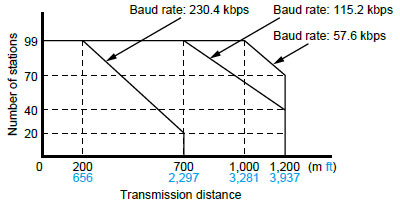 When using a transmission speed of 38.4 kbits/sec. or less, you can set up a maximum of 1,200 m 3,937 ft and 99 units. For RS-422 setting, you can set up a maximum transmission distance of 400 m 1,312 ft. |
| 4) | If mixed C-NET adapters are used, up to 32 units can be connected, but transmission speed will be limited to a maximum of 19.2 kbits/sec.. |
| 5) | The converter SI-35 manufactured by LINE EYE Co., Ltd.
is recommendable for the RS-485 at the computer side. When you use the SI-35, please adjust time after FP7 series PLC receives a command until it returns a response by a program. |
| 6) | RS-422 or RS-485 can be selected using the DIP switch built into the communication cassette. |
| 7) | Using the DIP switch built into the communication cassette allows the interface to be used as RS-232C 5-wire system × 1 channel. |
| 8) | 1:1 for RS-422 interface |
| Item | AFP7CCRET1 |
|---|---|
| Interface | Ethernet 100Base-TX / 10BASE-T |
| Communication speed | 100 Mbps, 10 Mbps Auto negotiation function |
| Total cable length | 100 m 328.084 ft (500 m 1,640.420 ft when a repeater is used) |
| Number of nodes | 254 units |
| Number of simultaneous connections | Max. 4 connections (User connection: 3, System connection: 1) |
| Communication protocol (Communication layer) | TCP / IP, UDP |
| DHCP | Automatic IP address acquisition |
| General-purpose communication | 4 kB / 1 connection |
| Dedicated communication | Slave communication (MEWTOCOL-COM, MEWTOCOL7-COM, MEWTOCOL-DAT) |
| Master communication (MEWTOCOL-COM, MEWTOCOL7-COM, MEWTOCOL-DAT) |
Notes :
| 1) | Please connect the Ethernet cable with the power turned off. |
|---|---|
| 2) | You cannot use this cassette "AFP7CCET1" with the serial communication unit. |
| 3) | Ethernet function (including FTP server / client function, HTTP client function, Web server function and E-mail sending function) cannot be used. |
Add-on cassettes (function cassettes)
ANALOG INPUT CASSETTE / ANALOG INPUT AND OUTPUT CASSETTE
Input specifications
| Item | AFP7FCRAD2 / AFP7FCRA21 | |
|---|---|---|
| Number of input points | 2 channels (non-insulated between channels) | |
| Input range | Voltage | 0 to 10 V / 0 to 5 V *Switch setting (individual settings possible) |
| Current | 0 to 20 mA | |
| Digital conversion value | K0 to K4000 | |
| Resolution | 1/4000 (12 bits) | |
| Conversion speed | 1 ms / channel | |
| Overall precision | ±1 % F.S. or less (0 to +55 ℃ +32 to +131 ℉) | |
| Input impedance | Voltage | 1 MΩ |
| Current | 250 Ω | |
| Absolute maximum input | Voltage | −0.5 V, +15 V |
| Current | 30 mA | |
| Insulation method | ・Between analog input terminal and internal digital circuit: transformer insulation, isolation IC insulation ・Between analog input terminal and analog output terminal: transformer insulation, isolation IC insulation |
|
| Connection method | Connector type terminal block | |
| Note : | Input specifications of the analog I/O cassette and analog input cassette are the same. |
|---|
ANALOG INPUT AND OUTPUT CASSETTE
Output specifications
| Item | AFP7FCRA21 | |
|---|---|---|
| Number of input points | 1 channel | |
| Output range | Voltage | 0 to 10 V / 0 to 5 V *Switch setting |
| Current | 0 to 20 mA | |
| Digital conversion value | K0 to K4000 | |
| Resolution | 1/4000 (12 bits) | |
| Conversion speed | 1 ms / channel | |
| Overall precision | ±1 % F.S. or less (0 to +55 ℃ +32 to +131 ℉) | |
| Output impedance | 0.5 Ω (voltage output) | |
| Max. output current | 10 mA (voltage output) | |
| Absolute output load resistance | 600 Ω or less (current output) | |
| Insulation method | ・Between analog input terminal and internal digital circuit: transformer insulation, isolation IC insulation ・Between analog input terminal and analog output terminal: transformer insulation, isolation IC insulation |
|
| Connection method | Connector type terminal block | |
| Note : | There is no analog output functionality in the analog input cassette. |
|---|
THERMOCOUPLE CASSETTE
Specifications
| Item | AFP7FCRTC2 | |
|---|---|---|
| Number of input points | 2 channels (insulated between channels) | |
| Input range* |
K type thermocouple | −50.0 to 500.0 ℃ −58.0 to 932.0 ℉ |
| J type thermocouple | −50.0 to 500.0 ℃ −58.0 to 932.0 ℉ | |
| Digital conversion value | Normal time | K−500 to K5000 |
| When range over | K−501, K5001 or K8000 | |
| When the thermocouple broken | K8000 | |
| When data preparation | K8001 | |
| Resolution | 0.2 ℃ (Display is 0.1 ℃ with the software averaging process.) |
|
| Sampling cycle | 100 ms / 2 channels | |
| Overall precision | ± 0.5 % F.S. or less and cold contact accuracy: 1.5 ℃ (0 to +55 ℃ +32 to +131 ℉) |
|
| Input impedance | 344 kΩ | |
| Insulation method | ・Between analog input terminal and internal digital circuit: transformer insulation, isolation IC insulation ・Between analog input terminal and analog output terminal: transformer insulation, isolation IC insulation |
|
| Connection method | Connector type terminal block | |
| Note : | Thermocouple setting can be switched with the switch on the front of the cassette. |
|---|
Digital input and output units
Input specifications
| Item | DC input units | |||
|---|---|---|---|---|
| 16 points type | 32 points type | 64 points type | ||
| Insulation method | Photocoupler | |||
| Rated input voltage | 12 to 24 V DC | 24 V DC | ||
| Rated input current | 6 mA approx. (at 24 V) | 2.7 mA | ||
| Impedance | 3.6 kΩ | 8.2 kΩ | ||
| Min. ON voltage / min. ON current | 9.6 V / 2 mA | 19.2 V / 2.5 mA | ||
| Max. OFF voltage / max. OFF current | 2.5 V / 1 mA | 5 V / 1.5 mA | ||
| Response time |
OFF→ON | 0.1 ms or less | 0.2 ms or less | |
| ON→OFF | 0.2 ms or less | 0.2 ms or less | ||
| Input points per common | 8 points / common | 32 points / common | ||
| Operating mode indicator | 16 points LED display (lights when ON) | 32 points LED display (lights when ON) | ||
| Connection method | Terminal block | 40-pin MIL connectors | ||
| Note : | Changeable by settable input time constant |
|---|
| Item | I/O mixed unit (input side) | ||
|---|---|---|---|
| DC input / sink output type | DC input / Source output type | ||
| Insulation method | Photocoupler | ||
| Rated input voltage | 24 V DC | ||
| Rated input current | 2.7 mA | 3.4 mA | |
| Impedance | 8.2 kΩ | 7.5 kΩ | |
| Min. ON voltage / min. ON current | 19.2 V / 2.5 mA | ||
| Max. OFF voltage / max. OFF current | 5 V / 1.5 mA | ||
| Response time |
OFF→ON | 0.2 ms or less (Note) | |
| ON→OFF | 0.2 ms or less (Note) | ||
| Input points per common | 32 points / common | ||
| Operating mode indicator | 32 points LED display (lights when ON, selectable by switch) | ||
| Connection method | 40-pin MIL connectors | ||
| Note : | Changeable by settable input time constant |
|---|
Output specifications
| Item | Relay output unit |
Transistor output units | I/O mixed unit (output side) |
||||
|---|---|---|---|---|---|---|---|
| 16 points type | 16 points (NPN) | 32 points (NPN) | 64 points (NPN) | 16 points (PNP) | 32 points (NPN) | ||
| Insulation method | Relay | Photocoupler | Photocoupler | ||||
| Nominal switching capacity |
2 A 250 V AC / 2 A 30 V DC |
- | - | - | - | - | |
| Min. load | 1 mA 100 mV DC (resistive load) |
- | - | - | - | - | |
| Output type | - | Open collector | |||||
| Rated load, voltage |
- | 5 to 24 V DC | |||||
| Operating load voltage range | - | 4.75 to 26.4 V DC | |||||
| Max. load current |
0.3 A (Y0 to Y7) |
- | 1 A | 0.3 A (26.4 to 20.4 V DC) 30 mA (4.75 V DC) |
0.3 A (20.4 to 26.4 V DC) 30 mA (4.75 V DC) |
1 A | 0.3 A (20.4 to 26.4 V DC) 30 mA (4.75 V DC) |
| 0.1 A (all) | - | 0.1 A (20.4 to 26.4 V DC) 15 mA (4.75 V DC) |
0.1 A (20.4 to 26.4 V DC) 15 mA (4.75 V DC) |
||||
| Common restriction | 5 A | 5 A | 3.2 A / common | 5 A | 3.2 A / common | ||
| Max. surge current | - | 3 A | 0.6 A | 3 A | 0.6 A | ||
| OFF state leakage current |
- | 1 μA or less | 1 μA or less | ||||
| ON state voltage drop | - | 0.5 V or less | 0.5 V or less | ||||
| Output points per common | 16 points / common | 16 points / common | 32 points / common | 16 points / common | 32 points / common | ||
| Operation mode indicator | 16 points LED display) | 16 points LED display) | 32 points LED display | 16 points LED display | 32 points LED display | ||
| Connection method | Terminal block | Terminal block | 40-pin MIL connectors | Terminal block | 40-pin MIL connectors | ||
| Item | Transistor output units | I/O mixed unit (output side) | ||
|---|---|---|---|---|
| Source type (PNP open collector) | ||||
| 32 points type | 64 points type | 32 points type | ||
| Insulation method | Photocoupler | |||
| Output type | Open collector | |||
| Rated load voltage | 5 to 24 V DC | |||
| Load voltage allowable range | 4.75 to 26.4 V DC | |||
| Max. load current |
0.3A A (Y0 to Y7) |
0.3 A (26.4 to 20.4 V DC) 30 mA (4.75 V DC) |
0.3 A (20.4 to 26.4 V DC) 30 mA (4.75 V DC) |
|
| 0.1 A (other than that above) |
0.1 A (20.4 to 26.4 V DC) 15 mA (4.75 V DC) |
|||
| Common restriction | 3.2 A/common | |||
| Max. surge current | 0.6 A | |||
| OFF state leakage current |
1 μA or less | |||
| ON state maximum voltage drop | 0.5 V or less | |||
| Repose time |
OFF→ON | 0.1 ms or less (at load current 2 mA or more) | ||
| ON→OFF | 0.5 ms or less (at load current 2 mA or more) | |||
| External power supply |
Voltage | 4.75 to 26.4 V DC | ||
| Current (at 24 V) |
130 mA | 90 mA/common | 90 mA | |
| Surge absorber | Zener diode | |||
| Short circuit protection | - | |||
| Output points per common | 32 points/common | |||
| Operating mode indicator |
32 points LED display (lights when ON) |
32 points LED display (lights when ON, selectable by switch) |
||
| External connection method |
Connector (MIL-compliant 40 pins) |
Connector (MIL-compliant 40 pins, two use) |
Connector (MIL-compliant 40 pins, one use) |
|
Analog input and output units
Analog input specifications
| Item | AFP7AD4H | AFP7AD8 | ||
|---|---|---|---|---|
| Number of channels | 4 channels | 8 channels | ||
| Input range (Resolution, Max. 16 bits) |
Voltage (Note 1) | -10 to +10 V (resolution: 1/62,500) 0 to 10 V (resolution: 1/31,250) 0 to 5 V (resolution: 1/31,250) 1 to 5 V (resolution: 1/25,000) (Note 2) |
||
| Current | 0 to 20 mA (resolution: 1/31,250) 4 to 20 mA (resolution: 1/25,000) (Note 2) |
|||
| Conversion speed |
Voltage / current | 25 μs/channel (at non-insulated channels) 5 ms/channel (at insulated channels) |
25 μs/channel (at non-insulated channels) | |
| Overall accuracy | ± 0.05 % F.S. or less (at +25 ℃ +77 ℉) ± 0.1 % F.S. or less (at 0 to +55 ℃ +32 to +131 ℉) |
± 0.1 % F.S. or less (at +25 ℃ +77 ℉) ± 0.3 % F.S. or less (at 0 to +55 ℃ +32 to +131 ℉) |
||
| Input impedance | Voltage input / Current input |
1 MΩ approx. / 250 Ω | ||
| Max. input range | -15 to +15 V voltage input -2 to +30 mA current input |
|||
| Insulation method |
Between input terminals and internal circuit |
Photocoupler and isolated DC/DC converter | ||
| Between channels | PhotoMOS relay | |||
| Digital processing |
Averaging | Number of times |
Setting range: 2 to 60,000 times | |
| Time duration |
Time setting range: 1 to 1,500 ms (at non-insulated channels), 200 to 60,000 ms (at insulated channels) | Time setting range: 1 to 1,500 ms (at non-insulated channels) | ||
| Moving | Range setting: 2 to 2,000 times | |||
| Scale conversion setting | Any value within ±30,000 | |||
| Offset setting | Any value within ±3,000 | |||
| Gain setting | Any value within 9,000 to 11,000 | |||
| Input range change method | Selectable per channel | |||
| Conversion execution / non-execution channel setting | Selectable per channel unit | |||
| Max. and min. value holding | Possible to make settings on a channel-bychannel basis | |||
| Comparison of upper and lower limit values |
Possible to make settings on a channel-bychannel basis (hysteresis) | |||
| Broken wire detection | When less than 0.7 V / 2.8 mA (only when voltage input range 1 to 5 V or current input range 4 to 20 mA is set.) | When less than 2.8 mA (only when current input range 4 to 20 mA is set.) | ||
| Buffer function | 3 trigger types: Soft trigger, External trigger and Input level |
|||
| Trigger input section |
Insulation method | Photocoupler | ||
| Rated input voltage / Rated input current |
24 V DC / 4.5 mA approx. (at 24 V DC) | 24 V DC / 12 mA approx. (at 24 V DC) | ||
| Input impedance | 5.1 kΩ approx. | 2 kΩ approx. | ||
| Operating voltage range | 21.6 to 26.4 V DC | |||
| Min. ON voltage / Min. ON current | 19.2 V / 3.5 mA | |||
| Max. OFF voltage / Max. OFF current | 5 V / 1.5 mA | |||
| Response time |
OFF→ON | 0.2 ms or less | 0.1 ms or less | |
| ON→OFF | 0.2 ms or less | 0.1 ms or less | ||
| Input points per common | 2 points/common | 1 point/common | ||
| Connection method | Terminal block (M3 terminal screw) | - | ||
Notes:
| 1) | Please note that the digital converted value corresponding to about 2 V of analog input is stored in the input relay area (WX) for channels which are not connected to input when setting the voltage range with AFP7AD8. |
|---|---|
| 2) | The full scale (F.S.) on the accuracy of an analog voltage input range from 1 to 5 V and that of an analog current input range from 4 to 20 mA are 0 to 5 V and 0 to 20 mA, respectively. |
Analog output specifications
| Item | AFP7DA4H | |
|---|---|---|
| Number of output channels | 4 channels | |
| Output range (Resolution, Max. 16 bits) |
Voltage | -10 to +10 V (resolution: 1/62,500) 0 to 10 V (resolution: 1/31,250) 0 to 5 V (resolution: 1/31,250) 1 to 5 V (resolution: 1/25,000) |
| Current | 0 to 20 mA (resolution: 1/31,250) 4 to 20 mA (resolution: 1/25,000) |
|
| Conversion speed |
Voltage / current | 25 μs/channel |
| Overall accuracy | ± 0.1% F.S. or less (at +25 ℃
+77 ℉) ± 0.3% F.S. or less (at 0 to +55 ℃ +32 to +131 ℉) |
|
| Output impedance (voltage output) | 0.5 Ω or less | |
| Max. output current (voltage output) | 10 mA | |
| Permissible output load resistance (Current output) |
500 Ω or less | |
| Insulation method |
Between the input terminals and internal circuit |
Photocoupler and isolated DC/DC converter |
| Between channels | Not insulated | |
| Scale conversion setting | Any value within ± 30,000 | |
| Offset and gain function |
Offset setting | Any value within ± 3,000 |
| Gain setting | Any value within 9,000 to 11,000 | |
| Output range change method | Selectable per channel | |
| Conversion execution/non execution channel setting |
Selectable per channel unit | |
| Upper and lower output limit clip function |
Possible to make settings on a channel-by-channel basis | |
| Analog output holding (in PROG mode) |
Present value/any value/not holding | |
| Connection method | Terminal block (M3 terminal screws) | |
Temperature input units
The temperature input units are compatible with the FP7 CPU units with firmware of Ver. 2.0 or later.
The compatible version of Control FPWIN GR7 is 2.2 or later.
Specifications for the thermocouple multiple analog input unit(AFP7TC8)
| Item | Specifications | ||
|---|---|---|---|
| Number of channels | 8 channels | ||
| Input range (resolution) |
Thermocouple (resolution: 0.1℃) |
K1:-100.0 to 600.0℃ / K2:-200.0 to 1000.0℃ | |
| J1:-100.0 to 400.0℃ / J2:-200.0 to 750.0℃ | |||
| T :-270.0 to 400.0℃ / N :-270.0 to 1300.0℃ | |||
| R : 0.0 to 1760.0℃ / S : 0.0 to 1760.0℃ | |||
| B : 0.0 to 1820.0℃ / E :-270.0 to 1000.0℃ | |||
| PLⅡ: 0.0 to 1390.0℃ / WRe5-26:0.0 to 2315.0℃ | |||
| Voltage | -10 to 10V DC(resolution: 1/62,500) 0 to 5V DC(resolution: 1/31,250) 1 to 5V DC(resolution: 1/25,000)(Note1) -100 to 100mV DC(resolution: 1/62,500) Resolution: max. 16 bits |
||
| Current | 0 to 20 mA (resolution: 1/31,250) 4 to 20 mA (resolution: 1/25,000) (Note 1) Resolution: max. 16 bits |
||
| Conversion speed | 5 ms/channel + 5 ms (Note 2) 25 ms/channel + 25 ms Add the drift compensation measuring time to the number of measuring channels. |
||
| Overall accuracy | ±0.1%F.S.or less(at +25℃ +77℉) ±0.3%F.S.or less(at 0 to +55℃ +32 to +131℉) |
||
| Reference contact compensation accuracy | ±1.0℃(with thermocouple input) | ||
| Input impedance |
Voltage / current | 1 MΩ / 250 Ω | |
| Insulation method |
Between input terminals and internal circuit | Photocoupler and isolated DC/DC converter |
|
| Between channels | PhotoMOS relay | ||
| Conversion execution / non-execution channel setting |
Selectable per channel unit | ||
| Input range change method | Selectable per channel | ||
| Digital processing |
Averaging | Cycle, time, moving | |
| Scale conversion setting | Any value within ±30,000 (Voltage and current range only) | ||
| Offset setting | Any value within ±3,000 | ||
| Gain setting | ±10% | ||
| Comparison of upper and lower limit values | Selectable for one channel | ||
| Max. and min. value holding | Selectable for one channel | ||
| Broken wire detection | Available | ||
| Connection method | Connector type terminal block | ||
Notes :
| 1) | The full scale (F.S.) ranges of accuracy are 1 to 5 V DC for voltage and 0 to 20 mA for current input, respectively. |
|---|---|
| 2) | The AC noise removal is disabled. |
Specifications for the resistance temperature detector input unit(AFP7RTD8)
| Item | Specifications | ||
|---|---|---|---|
| Number of channels | 8 channels | ||
| Input range (resolution) |
Resistance temperature detector (resolution: 0.1℃) |
Pt100 (1): -100.0 to 200.0℃ Pt100 (2): -200.0 to 650.0℃ JPt100(1): -100.0 to 200.0℃ JPt100(2): -200.0 to 650.0℃ Pt1000: -100.0 to 100.0℃ |
|
| Conversion speed | 25 ms/channel + 25 ms Add the drift compensation measuring time to the number of measuring channels. |
||
| Overall accuracy | ±0.1%F.S.or less(at +25℃ +77℉) ±0.3%F.S.or less(at 0 to +55℃ +32 to +131℉) |
||
| Allowable signal source resistance | R.T.D. input: 30 Ω(three wires balanced) | ||
| Insulation method |
Between input terminals and internal circuit |
Photocoupler and isolated DC/DC converter |
|
| Between channels | PhotoMOS relay | ||
| Conversion execution / non-execution channel setting |
Selectable per channel unit | ||
| Input range change method | Selectable per channel | ||
| Digital processing |
Averaging | Cycle, time, moving | |
| Offset setting | Any value within ±3,000 | ||
| Gain setting | ±10% | ||
| Comparison of upper and lower limit values | Selectable for one channel | ||
| Max. and min. value holding | Selectable for one channel | ||
| Broken wire detection | Available | ||
| Connection method | Connector type terminal block | ||
Multi input/output unit
Function specifications
| Item | AFP7MXY32DWD | ||
|---|---|---|---|
| Basic input and output |
Number of occupied I/O points | Input/Output: 64 points each (4 words) | |
| Number of external I/O points | Input: 16 points, Output: 16 points | ||
| Input time constant setting |
None, 0.5 μs, 1 μs, 2 μs, 4 μs, 8 μs, 16 μs, 32 μs, 64 μs, 96 μs, 128 μs, 256 μs, 2 ms, 4 ms or 8 ms Setting possible in 2-point units |
||
| Output polarity setting | No output, N channel, P channel, both channels (push pull output), and differential output Setting possible in 4-point units |
||
| Interrupt | Number of points | 8 points/unit (Max. of 8 units can be used with FP7 system when setting interrupt mode.) |
|
| Mode | Non-interrupt unit, interrupt unit (Set using DIP switches) |
||
| Interrupt condition setting | Terminal input, Comparison match | ||
| Counter | Counter type | Ring counter Linear counter |
|
| Input mode | Direction discrimination, individual input, phase input | ||
| Number of channels | 4 channels (Note 1) | ||
| Counting range | Signed 32 bit (-2,147,483,648 to +2,174,483,647) Setting possible of upper and lower limits |
||
| Max. countable speed | 5 V input voltage: 500 kHz (Note 2) 12 V input voltage: 500 kHz (350 kHz with phase input) (Note 2) 24 V input voltage: 250 kHz (180 kHz with phase input) (Note 2) |
||
| Min. input pulse width | 0.5 μs | ||
| Comparison output setting |
Max. 8 points Terminal input counter: 4 channels |
||
| Others | Transfer multiplication function (× 1, × 2, × 4) Elapsed value offset / preset function Elapsed value hold function, setting of upper / lower count limits Input pulse frequency measurement Overflow / underflow detection |
||
| Pulse output |
Number of channels | 4 channels | |
| Output mode | Direction discrimination, individual input, phase input, comparison match stop | ||
| Output terminals |
Pulse output function |
2 terminals / channel (B11 to B18 terminals) | |
| PWM output function |
1 terminal / channel (B11, B13, B15 and B17 terminals) | ||
| Output frequency |
Pulse output function |
1 to 500 kHz (Note 3) (1 Hz increments) | |
| PWM output function |
1 to 100 kHz (Note 3) (1 Hz increments) | ||
| Duty | Pulse output function |
50 % approx. (fixed) | |
| PWM output function |
0 to 100 % [Set in 0.1% increments (Note 4)] | ||
| Other functions | Pulse number measurement function (dedicated pulse counter 4 channels) | ||
Notes:
| 1) | When using elapsed value hold function, number of channels will be limited. |
|---|---|
| 2) | With 50 % duty input pulse. |
| 3) | When push pull setting or output current is 0.1 A. Varies according to load. |
| 4) | Will be set in 1 % increments when output frequency exceeds 10 kHz. |
High-speed Counter Units
| Type | 2 ch type | 4 ch type | ||
|---|---|---|---|---|
| Model No. | AFP7HSC2T | AFP7HSC4T | ||
| Input | Insulation method | Photocoupler | ||
| Rated input voltage | 12 to 24 V DC / 3.5 to 5 V DC | |||
| Input impedance |
24 V DC | 3.0 kΩ approx. | ||
| 5 V DC | 390 Ω approx. | |||
| Usage voltage range | 24 V DC | 10.8 to 26.4 V DC | ||
| 5 V DC | 3.5 to 5.25 V DC | |||
| Min. ON voltage / Min. ON current |
24 V DC | 10 V DC / 4 mA | ||
| 5 V DC | 3.0 V DC / 4 mA | |||
| Max. OFF voltage / Max. OFF current |
24 V DC | 2.0 V DC / 2 mA | ||
| 5 V DC | 1.0 V DC / 0.5 mA | |||
| Input time constant setting | None, 0.1 μs, 0.2 μs, 0.5 μs, 1.0 μs, 2.0 μs, 10.0 μs | |||
| Count function |
No. of counters | 2 ch | 4 ch | |
| Counter type | Linear counter / Ring counter | |||
| Counting range | Signed 32-bit ( -2,147,483,648 to +2,147,483,647 ) | |||
| Max. input frequency | 4 MHz / 8 MHz for individual input (phases A and B) (Duty ratio 50 ± 10 %) 4 MHz / 8 MHz for direction discrimination input (Duty ratio 50 ± 10 %) 4 MHz / 8 MHz /16 MHz for 2-phase input (Duty ratio 50 ± 10 %, Phase shifting below 5 %) |
|||
| Input signal | Phases A, B and Z | |||
| External I/O | Control signal input: 4 points (2 points/ch) External output: 4 points (2 points/ch) |
Control signal input: 8 points (2 points/ch) External output: 8 points (2 points/ch) |
||
| Counter input type | Individual input: 1 multiple, 2-multiple Direction discrimination input: 1 multiple, 2-multiple 2-phase input: 1 multiple, 2-multiple, 4-multiple |
|||
| Measurement function |
Frequency measurement function | Measures the intervals between the variations of count values, and calculates the frequency. | ||
| Comparison function |
Target value match function | Depending on the count direction, sets or resets the output when the counter value reaches the target value. | ||
| External output |
Comparison result output function | Outputs the result of comparison function. | ||
| Other functions |
Capture function | Acquires the current count value from the edges of input signals, and stores it in the capture 0 register or capture 1 register. The value of the specified capture register will be overwritten by a new value and the old value will be discarded every time a counter value is captured. | ||
| Interrupt input function | Available (2 points/ch, Max. 8 points/unit) (Note 1, 2) | |||
Notes :
| 1) | The interrupt input function can be used for 8 points per unit and for a maximum of 8 units (max. 64 points) in the whole system. However, the entire scan time slows down as more interrupt programs are used. Minimize the use of interrupt programs. |
|---|---|
| 2) | The priority order for interrupt inputs is as follows; In a unit, from the smallest interrupt bit. In the whole system, from the smallest unit number. from the smallest unit number. |
Motion control units
| Item | 16 axes type | 32 axes type | 64 axes type | ||||
|---|---|---|---|---|---|---|---|
| Connected slave (Note 1, 2, 3) |
Panasonic AC servo motor MINAS A6B / A5B series EtherCAT-compatible S-LINK V gateway controller SL-VGU1-EC |
||||||
| Number of control axes | Real axis : 16 axes Virtual axis : 8 axes |
Real axis : 32 axes Virtual axis : 16 axes |
Real axis : 64 axes Virtual axis : 32 axes |
||||
| Communication cycle | 0.5 ms / 1 ms / 2 ms / 4ms | ||||||
| Interpolation control | 2-axis linear interpolation, 2-axis circular interpolation, 3-axis linear interpolation and 3-axis spiral interpolation |
||||||
| Number of occupied I/O points | Input: 16 points, Output: 16 points | ||||||
| Automatic operation | Positioning control (CSP) | Position specification method | Absolute (specified absolute position), Increment (specified relative position) | ||||
| Position specified unit | pulse μm (select a minimum instruction unit of 0.1 μm or 1 μm) inch (select a minimum instruction unit of 0.00001 inch or 0.0001 inch) degree (select a minimum instruction unit of 0.1 degree or 1 degree) |
||||||
| Position reference range | pulse : −2,147,483,648 to 2,147,483,647pulse μm (0.1μm) : −214,748,364.8 to 214,748,364.7μm μm (1μm) : −2,147,483,648 to 2,147,483,647μm inch (0.00001inch) : −21,474.83648 to 21,474.83647inch inch (0.0001inch) : −214,748.3648 to 214,748.3647inch degree (0.1degree) : −214,748,364.8 to 214,748,364.7degree degree (1degree) : −2,147,483,648 to 2,147,483,647degree |
||||||
| Speed reference range | pulse: 1 to 2,147,483,647 pps μm: 1 to 2,147,483,647 μm/sec. inch: 0.001 to 2,147,483.647 inch/sec. degree: 0.001 to 2,147,483.647 rev/sec. |
||||||
| Acceleration/ deceleration type |
Linear acceleration/deceleration, S-shaped acceleration/deceleration |
||||||
| Acceleration/ deceleration time |
0 to 10,000ms(adjustable in 1 ms increments) | ||||||
| Number of positioning tables |
Each axis standard area: 1,000 points expansion area 100 points (24 axes in case of using simultaneous startup) |
||||||
| Control method |
Independent | PTP control (E point control, C point control), CP control (P point control), Speed control (J point control) | |||||
| 2-axis interpolation | Linear interpolation | E point, P point and C point controls: Specify synthesis speed or major axis speed | |||||
| Circular interpolation | E point, P point and C point controls: Center point or passing point | ||||||
| 3-axis interpolation | Linear interpolation | E point, P point and C point controls: Specify synthesis speed or major axis speed | |||||
| Spiral interpolation | E point, P point and C point controls: Center point or passing point | ||||||
| Other function | Dwell time | 0 to 32,767ms (adjustable in 1 ms increments) | |||||
| Manual operation | JOG/inching operation | Speed reference range | pulse: 1 to 2,147,483,647 pps μm: 1 to 2,147,483,647 μm/sec. inch: 0.001 to 2,147,483.647 inch/sec. degree: 0.001 to 2,147,483.647 rev/sec. |
||||
| Acceleration/ deceleration type |
Linear acceleration/deceleration, S-shaped acceleration/deceleration |
||||||
| Acceleration/ deceleration time |
0 to 10,000ms (adjustable in 1 ms increments) | ||||||
| Home return | Speed reference range | pulse: 1 to 2,147,483,647 pps μm: 1 to 2,147,483,647 μm/sec. inch: 0.001 to 2,147,483.647 inch/sec. degree: 0.001 to 2,147,483.647 rev/sec. |
|||||
| Acceleration/ deceleration type |
Linear acceleration/deceleration, S-shaped acceleration/deceleration |
||||||
| Acceleration/ deceleration time |
0 to 10,000ms (adjustable in 1 ms increments) | ||||||
| Return methods | DOG method (4 types), Limit method (2 types), Data set method, Z phase method, Stop-on-contact method (2 types) | ||||||
| Stop function | Deceleration stop | Deceleration time | Axis operation mode startup time of activated axis | ||||
| Emergency stop | Deceleration time | 0 to 10,000 ms (adjustable in 1 ms increments) | |||||
| Limit stop | Deceleration time | 0 to 10,000 ms (adjustable in 1 ms increments) | |||||
| Error stop | Deceleration time | 0 to 10,000 ms (adjustable in 1 ms increments) | |||||
| System stop | Deceleration time | Immediate stop (1 ms), all axes stop | |||||
| Synchronous operation function | Synchronous basic setting | Master axis | Selection possible of real axis and virtual axis | ||||
| Slave axis | Virtual axis: Max. 8 axes/master |
Virtual axis: Max. 16 axes/master |
Virtual axis: Max. 32 axes/master |
||||
| Electronic gear function | Operation setting | Gear ratio setting | |||||
| Operation method | Direct method, Acceleration/deceleration method | ||||||
| Electronic clutch function | Clutch ON trigger | Contact input | |||||
| Clutch method | Direct method, Linear slide method | ||||||
| Electronic cam function | Cam curve | Select from 20 types Multiple curves can be specified within a phase (0 to 100 %). |
|||||
| Resolution | 1024, 2048, 4096, 8192, 16384, 32768 | ||||||
| Number of cam patterns | 16 to 64 (Depends on resolution) |
32 to 128 (Depends on resolution) |
64 to 256 (Depends on resolution) |
||||
| Other specifications | Software limit function | Set range | pulse : −2,147,483,648 to 2,147,483,647pulse μm (0.1μm) : −214,748,364.8 to 214,748,364.7μm μm (1μm) : −2,147,483,648 to 2,147,483,647μm inch (0.00001inch) : −21,474.83648 to 21,474.83647inch inch (0.0001inch) : −214,748.3648 to 214,748.3647inch degree (0.1degree) : −214,748,364.8 to 214,748,364.7degree degree (1degree) : −2,147,483,648 to 2,147,483,647degree |
||||
| Monitor judgment |
Torque judgment | Torque judgment Selection possible of active/non-active and error/warning 0.0 to ±500.0 % |
|||||
| Actual speed judgment |
Actual speed judgment Selection possible of active/non-active and error/warning 0.0 to ±5,000 rpm |
||||||
| Backup | Parameters and positioning data are saved to flash memory (battery free) | ||||||
| ・Limit input CWL, CCWL monitor and proximity (DOG) monitor ・General-purpose input: 5 points, General-purpose output: 1 point (I/O from AMP) ・Auxiliary output contact and auxiliary output cord |
|||||||
Notes:
| 1) | A6B and SL-VGU1-EC are compatible with the FP7 motion control unit Ver.1.2 or later. |
|---|---|
| 2) | One unit or more A6B or A5B must exist on the network. Also, A6B and A5B can both be used on the network. |
| 3) | The hub for EtherCAT / Ethernet cannot be used. |
Positioning units
Performance specifications
| Item | Specifications | |||||||
|---|---|---|---|---|---|---|---|---|
| 2 axes type | 4 axes type | |||||||
| Part No. | AFP7PP02T | AFP7PP02L | AFP7PP04T | AFP7PP04L | ||||
| Output type | Transistor | Line driver | Transistor | Line driver | ||||
| Max. operation speed | 500 kpps | 4 Mpps | 500 kpps | 4 Mpps | ||||
| Number of axes controlled | 2 axes | 4 axes | ||||||
| Interpolation control | 2 axes linear interpolation, 2 axes circular interpolation |
2 axes linear interpolation, 3 axes linear interpolation, 2 axes circular interpolation, 3 axes spiral interpolation |
||||||
| Position command units | pulse μm (The minimum command unit can be selected from 0.1 μm or 1 μm.) inch (The minimum command unit can be selected from 0.00001 inch or 0.0001 inch.) degree (The minimum command unit can be selected from 0.1 degree or 1 degree.) |
|||||||
| Position command range | pulse: −1,073,741,823 to +1,073,741,823 pulse μm (0.1 μm): −107,374,182.3 to +107,374,182.3 μm μm (1 μm): −1,073,741,823 to +1,073,741,823 μm inch (0.00001 inch): −10,737.41823 to +10,737.41823 inch inch (0.0001 inch): −107,374.1823 to +107,374.1823 inch degree (0.1 degree): −107,374,182.3 to +107,374,182.3 degree degree (1 degree): −1,073,741,823 to +1,073,741,823 degree |
|||||||
| Speed command range | pulse: 1 to 32,767,000 pps μm: 1 to 32,767,000 μm/sec inch: 0.001 to 32,767.000 inch/sec degree: 0.001 to 32,767.000 rev/sec *Specify an output speed that is below the maximum operating speed. |
|||||||
| Automatic operation |
Position control |
Position command method | Absolute (Absolute position designation), Increment (Relative position designation) |
|||||
| Acceleration / deceleration method | Linear acceleration / deceleration, S-curve acceleration / deceleration | |||||||
| Acceleration time | 0 to 10,000 ms (in increments of 1 ms) | |||||||
| Deceleration time | 0 to 10,000 ms (in increments of 1 ms) | |||||||
| Number of positioning tables per axis | Standard area: 600 points, expansion area: 25 points | |||||||
| Control method |
Independent | PTP control (E point control, C point control), CP control (P point control), Speed control (J point control) | ||||||
| 2-axis interpolation |
Linear | E point, P point and C point controls: Specify synthesis speed or major axis speed | ||||||
| Circular | E point, P point and C point controls: center point or passing point | |||||||
| 3-axis interpolation |
Linear | E point, P point and C point controls: Specify synthesis speed or major axis speed | ||||||
| Spiral | E point, P point and C point controls: center point or passing point | |||||||
| Startup time | Standard area: 3 ms or less, expansion area: 5 ms or less | |||||||
| Other function |
Dwell time |
0 to 32,767 ms (in increments of 1 ms) | ||||||
| Manual operation |
JOG operation |
Acceleration / deceleration method |
Linear acceleration / deceleration, S-curve acceleration / deceleration |
|||||
| Acceleration / deceleration time |
0 to 10,000 ms (in increments of 1 ms) | |||||||
| Home return |
Acceleration / deceleration method |
Linear acceleration / deceleration | ||||||
| Acceleration / deceleration time |
0 to 10,000 ms (in increments of 1 ms) | |||||||
| Return methods | 7 methods: DOG method (3 types), Limit method (2 types), Data set method, Z-phase method | |||||||
| Pulser operation |
Speed command range | Operates in synchronization with pulser input | ||||||
| Stop function | Deceleration stop | Deceleration time | Deceleration time of running operation | |||||
| Emergency stop | Deceleration time | 0 to 10,000 ms (in increments of 1 ms) | ||||||
| Limit stop | Deceleration time | 0 to 10,000 ms (in increments of 1 ms) | ||||||
| Error stop | Deceleration time | 0 to 10,000 ms (in increments of 1 ms) | ||||||
| System stop | Deceleration time | Immediate stop (0 ms), all axes stop | ||||||
| Synchronous operation function | Synchronous basic setting |
Master axis | Existing axes, virtual axes or pulse input (1 to 4) | |||||
| Slave axis | Max. 2 axes | Max. 4 axes | ||||||
| Electronic gear function |
Operation setting | Gear ratio setting | ||||||
| Operation method | Direct method, Acceleration / deceleration method | |||||||
| Electronic clutch function |
Clutch ON trigger | Contact input | ||||||
| Clutch method | Direct method, Linear slip method | |||||||
| Electronic cam function |
Cam curve | Select from 20 types Multiple curves can be specified within a phase (0 to 100%). |
||||||
| Resolution | 1024, 2048, 4096, 8192, 16384, 32768 | |||||||
| Number of cam patterns |
4 to 16 (Depends on resolution) | |||||||
| Other specifications | Output mode | 1 pulse output (pulse + direction), 2 pulse outputs (CW / CCW) |
||||||
| High-speed counter function (Note) |
Countable range | −1,073,741,823 to +1,073,741,823 pulse | ||||||
| Input mode | Phase difference input, Direction distinction input, Individual input (transfer multiple available for each) |
|||||||
| Built-in servo ON output | ||||||||
| Note: | Pulser input and high-speed counter functions cannot be used simultaneously, as the same pulse input terminal is used. |
|---|
Pulse Output Units
Performance specifications
| Item | Specifications | ||||
|---|---|---|---|---|---|
| Part No. | AFP7PG02T | AFP7PG04T | AFP7PG02L | AFP7PG04L | |
| Output type | Transistor | Line driver | |||
| Occupied points | Each 32 points of I/O | Each 64 points of I/O | Each 32 points of I/O | Each 64 points of I/O | |
| Number of axes controlled | 2 axes, independent | 4 axes, independent | 2 axes, independent | 4 axes, independent | |
| Position command | Command units | Pulse (The program specifies whether increment or absolute is used.) | |||
| Max. pulse count | Signed 32 bits (+2,147,483,647 to -2,147,483,648 pulses) | ||||
| Speed command | Command range | 1 pps to 500 kpps (can set in 1 pps) | 1 pps to 4 Mpps (can set in 1 pps) | ||
| Acceleration/ deceleration command |
Acceleration / deceleration |
Linear acceleration / deceleration, S acceleration / deceleration | |||
| "S" Acceleration / deceleration |
Can select from sin curve, secondary curve, cycloid curve and third curve. | ||||
| Acceleration / deceleration time |
0 to 32,767 ms (can set in 1 ms) | ||||
| Home return | Home return speed | Speed setting possible (changes return speed and search speed) | |||
| Input signal | Home input, near home input, limit input (+), limit input (−) | ||||
| Output signal | Deviation counter clear signal | ||||
| Operation mode |
E point control (linear and s acceleration/decelerations) P point control (linear and s acceleration/decelerations) Home return operation (home search) JOG operation (Note 1) JOG positioning operation Pulser input function (Note 2) transfer multiplication ratio (× 1, × 2, × 5, × 10, × 50, × 100, × 500, × 1000) Real-time frequency change Infinity output |
||||
| Startup time | 0.02 ms, 0.005 ms or 0.001 ms selecting possible (Note 3) | ||||
| Output interface | Output mode | 1 pulse output (pulse and sign), 2 pulse output (CW and CCW) | |||
| High-speed counter function (Note 2) |
Countable range | Signed 32 bits (+2,147,483,647 to -2,147,483,648 pulse) | |||
| Input mode | Two-phase input, direction distinction input, individual input (with multiplier function mode) | ||||
| Other functions | Startup using I/O contact Built-in limit (+) and limit (−) With servo ON output |
||||
| External power supply | Voltage | 21.6 to 26.4 V DC | |||
| current | 50 mA (at 24 V) | 90 mA (at 24 V) | 50 mA (at 24 V) | 90 mA (at 24 V) | |
Notes :
| 1) | When linear acceleration/deceleration operation is selected, it is possible to change the target speed during operation. |
|---|---|
| 2) | Since the pulsar input function and the high-speed counter function use the same pulse input terminal, both functions cannot be used at the same time. |
| 3) | Startup time can be changed using the common memory control code setting. The factory (default) setting is 0.02 ms. Startup time is defined as the time between startup and output of the first pulse. |
Power supply units
Specifications
| Item | Specifications | |
|---|---|---|
| Part No. | AFP7PSA1 | AFP7PSA2 |
| Rated input voltage | 100-240 V AC | |
| Allowable input voltage range | 85-264 V AC | |
| Input power supply frequency | 47 to 63 Hz | |
| Inrush current | 40 A or less (Note 2) | |
| Input current | 0.75 A or less | 1.25 A or less |
| Rated output current (at 24 V) | 1.0 A | 1.8 A |
| Alarm contact capacity | 1 A (30 V DC) | |
| Remaining lifespan counter | Not available | Available (Note 1) |
Notes :
| 1) | Alarm by CPU unit |
|---|---|
| 2) | On cold starting |
| 3) | Power supply unit cannot be used with AFP7CPS2R CPU unit. |
Serial Communication Unit
Specifications
| Item | AFP7NSCR |
|---|---|
| Number of communication cassette installations | Max. 2 cassettes |
| Number of installations to CPU unit | Max. 8 units |
| Note : | Communication cassette AFP7CCRET1 is not supported. |
|---|
Multi-wire link unit
| Item | AFP7MW | ||
|---|---|---|---|
| Mode | W mode | W2 mode | F mode |
| Communication method | Token bus method | Polling method | |
| Transmission method | Baseband transmission method | ||
| Transmission speed | 500 kbits/sec. | 500 kbits/sec., 250 kbits/sec. | 500 kbits/sec. |
| Transmission distance |
Extendable to 800 m 2,624.672 ft |
Extendable to 800 m 2,624.672 ft (500 kbits/sec.) Extendable to 1,200 m 3,937.008 ft (250 kbits/sec.) |
Extendable to 700 m 2,296.588 ft |
| Number of connectable stations |
Max. 32 stations | 1 master station + Max. 32 slave stations |
|
| Transmission error check | CRC (Cyclic Redundancy Check) system | ||
| Synchronous method | Start-stop synchronization | ||
| Interface | RS485 compatible | ||
| Transmission cable | Twisted-pair cable | Twisted-pair cable, VCTF cable |
|
| RAS function | Hardware self-diagnosis function | ||
PHLS (remote I/O) units
Communication specifications (common)
| Item | Specifications |
|---|---|
| Communication method | Two-wire system half duplex |
| Insulation method | Pulse transformer insulation |
| Communication speed | 6 Mbps / 12 Mbps |
| Synchronous method | Bit synchronization |
| Error check | CRC-12 |
| Communication distance | Total length 200 m 656 ft (at 6 Mbps) / 100 m 328 ft (at 12 Mbps) (Note) |
| Connection method | Multi-drop method |
| Impedance | 100 Ω |
| Terminator | Mounted on unit |
| External interface | Master unit: terminal block (2 channels) Slave unit (standard type): screw-type terminal block Slave unit (compact type): connector-type terminal block |
| Note : | Performance when the recommended cable is used Use of the recommended cable is necessary to achieve the maximum transmission distance and number of slave units. |
|---|
Input side specifications
| Item | Specifications | ||
|---|---|---|---|
| Standard type | Compact type | ||
| Insulation method | Photocoupler | Non-isolated | |
| Rated input voltage | 24 V DC | ||
| Rated input current | 3 mA approx. | 4.3 mA approx. | |
| Input impedance | 7.5 kΩ approx. | 5.6 kΩ approx. | |
| Min. ON voltage / Min. ON current | 15 V / 2 mA | 17 V / 2 mA | |
| Max. OFF voltage / Max. OFF current | 5 V / 0.5 mA | ||
| Response time | OFF→ON | 1 ms or less | |
| ON→OFF | 1 ms or less | ||
・Recommended cable for conforming to EMC Directive
Please note that standard type AFPRP1□ conforms to EMC Directive when used with recommended cable as below (except for AFPRP2□).
ZHY221PS made by Shinko Seisen Industry Co., Ltd.
Characteristics
- AWG22 to AWG26, twisted pair cable
- Characteristics impedance: 100 Ω
- Insulation: crosslinked polyethylene foam
| Note : | If the recommended cable is not used, it may not be possible to reach the maximum transfer distance or performance with the maximum number of slaves. Please configure the wiring collinearly on all system. |
|---|
Output side specifications (except relay)
| Item | Specifications | ||
|---|---|---|---|
| Standard type | Compact type (except relay) |
||
| Insulation method | Photocoupler | Non-isolated | |
| Output type | Sink type (Open collector output) | ||
| Rated load voltage | 20.4 to 28.8 V DC | ||
| Max. control capacity | 0.1 A/point | ||
| Max. surge current | 0.5 A | ||
| OFF state leakage current | 0.1 mA or less | ||
| ON state maximum voltage drop | 0.5 V or less | ||
| Repose time | OFF→ON | 0.05 ms or less | |
| ON→OFF | 0.5 ms or less | ||
| Surge absorber | Zener diode | ||
| Short circuit protection | None | ||
Output side specifications (relay)
| Item | Specifications | |
|---|---|---|
| Compact type (relay) | ||
| Insulation method | Relay insulation | |
| Rated control capacity | 1 A 250 V AC (2 A/common) 1 A 30 V DC (2 A/common) |
|
| Min. load | 0.1 mA 100 mV (resistive load) | |
| Repose time | OFF→ON | 10 ms or less |
| ON→OFF | 5 ms or less | |
| Life time | Mechanical life | 2 × 10⁷ operations or more |
| Electrical life | 1 × 10⁵ operations or more (switching frequency: 20 times/minute) |
|
| Surge absorber | None | |
| Short circuit protection | None | |
General specifications on each units
Common general specifications
| Item | Specifications |
|---|---|
| Ambient temperature | 0 to +55 ℃ +32 to +131 ℉, Storage: -40 to +70 ℃ -40 to +158 ℉ |
| Ambient humidity | 10 to 95 % RH (at +25 ℃ +77 ℉, no condensation), Storage: 10 to 95 % RH (at +25 ℃ +77 ℉, no condensation) |
| Vibration resistance | 5 to 8.4 Hz, single amplitude of 3.5 mm 0.138 in, 1 sweep/min. (IEC 61131-2); 8.4 to 150 Hz, constant acceleration of 9.8 m/s2, 1 sweep/min. (IEC 61131-2), 10 times each in X, Y, and Z directions |
| Shock resistance | 147 m/s2 or more , 3 times each in X, Y, and Z directions (IEC 61131-2) |
| Noise immunity | 1,000 V [p-p] with pulse width 50 ns and 1 μs (using a noise simulator) |
| Operating condition | Free from corrosive gasses and excessive dust |
Notes :
| 1) | Please refer to the user's manual for details of breakdown voltage and insulation resistance. |
|---|
Individual general specifications
| Item | CPU units | Expansion units | ||||
|---|---|---|---|---|---|---|
| AFP7CPS4RE(S) | AFP7CPS3RE(S) | AFP7CPS3R(S) | AFP7CPS2R | AFP7EXPM | AFP7EXPS | |
| Rated voltage range | 20.4 to 28.8 V DC | - | 20.4 to 28.8 V DC | |||
| Current consumption | 200 mA or less | 150 mA or less | 120 mA or less (Note 1) |
100 mA or less (Note 1) |
||
| Net weight | 220 g approx. (with terminal block and end unit) |
180 g approx. (with terminal block and end unit) |
120 g approx. | 200 g approx. (with end unit) |
||
| Item | Communication cassettes | |||||
|---|---|---|---|---|---|---|
| AFP7CCRS1 | AFP7CCRS2 | AFP7CCRM1 | AFP7CCRM2 | AFP7CCRS1M1 | AFP7CCRET1 | |
| Rated voltage range | - | - | - | - | - | - |
| Current consumption | 35 mA or less (Note 2) |
60 mA or less (Note 2) |
60 mA or less (Note 2) |
90 mA or less (Note 2) |
70 mA or less (Note 2) |
35 mA or less (Note 2) |
| Net weight | 25 g approx. (with terminal block) | 20 g approx. | ||||
| Item | Function cassettes | ||
|---|---|---|---|
| AFP7FCRAD2 | AFP7FCRA21 | AFP7FCRTC2 | |
| Rated voltage range | - | - | - |
| Current consumption | 40 mA or less (Note 2) |
75 mA or less (Note 2) |
45 mA or less (Note 2) |
| Net weight | 25 g approx. (with terminal block) | ||
| Item | Input and output units | ||||
|---|---|---|---|---|---|
| AFP7X16DW | AFP7X32D2 | AFP7X64D2 | AFP7Y16R | AFP7Y16T | |
| Rated voltage range | - | - | - | - | - |
| Current consumption | 25 mA or less | 30 mA or less | 35 mA or less | 180 mA or less | 35 mA or less |
| Net weight | 125 g approx. | 95 g approx. | 110 g approx. | 180 g approx. | 125 g approx. |
| Item | Input and output units | ||||
|---|---|---|---|---|---|
| AFP7Y32T | AFP7Y64T | AFP7Y16P | AFP7Y32P | AFP7Y64P | |
| Rated voltage range | - | - | - | - | - |
| Current consumption | 50 mA or less | 75 mA or less | 35 mA or less | 50 mA or less | 75 mA or less |
| Net weight | 95 g approx. | 115 g approx. | 125 g approx. | 95 g approx. | 115 g approx. |
| Item | Input and output units | Analog input and output units | |||
|---|---|---|---|---|---|
| AFP7XY64D2T | AFP7XY64D2P | AFP7AD8 | AFP7AD4H | AFP7DA4H | |
| Rated voltage range | - | - | - | - | - |
| Current consumption | 55 mA or less | 55 mA or less | 85 mA or less | 100 mA or less | 250 mA or less |
| Net weight | 115 g approx. | 115 g approx. | 130 g approx. | 130 g approx. | 130 g approx. |
| Item | Temperature input units | |
|---|---|---|
| AFP7TC8 | AFP7RTD8 | |
| Rated voltage range | - | - |
| Current consumption | 80 mA or less | 65 mA or less |
| Net weight | 145 g approx. | 145 g approx. |
| Item | High-speed counter units | Positioning units | ||||
|---|---|---|---|---|---|---|
| AFP7HSC2T | AFP7HSC4T | AFP7PP02T | AFP7PP04T | AFP7PP02L | AFP7PP04L | |
| Rated voltage range | - | - | - | - | - | - |
| Current consumption | 65 mA or less | 120 mA or less | 120 mA or less | 120 mA or less | 120 mA or less | |
| Net weight | 130 g approx. | 145 g approx. | 145 g approx. | 145 g approx. | 145 g approx. | |
| Item | Pulse output units | |||
|---|---|---|---|---|
| AFP7PG02T | AFP7PG04T | AFP7PG02L | AFP7PG04L | |
| Rated voltage range | - | - | - | - |
| Current consumption | 65 mA or less | 65 mA or less | 65 mA or less | 65 mA or less |
| Net weight | 130 g approx. | 150 g approx. | 130 g approx. | 150 g approx. |
| Item | Motion control unit | Multi input/output unit | ||
|---|---|---|---|---|
| AFP7MC16EC | AFP7MC32EC | AFP7MC64EC | AFP7MXY32DWD | |
| Rated voltage range | - | - | - | - |
| Current consumption | 180 mA or less | 180 mA or less | 180 mA or less | 100 mA or less |
| Net weight | 150 g approx. | 150 g approx. | 150 g approx. | 100 g approx. |
| Item | Serial communication unit | Power supply units | Multi-wire link unit | |
|---|---|---|---|---|
| AFP7NSCR | AFP7PSA1 | AFP7PSA2 | AFP7MW | |
| Rated voltage range | - | 100 to 240 V AC | - | |
| Current consumption | 50 mA or less (when without add-on cassette) | 750 mA or less | 1,250 mA or less | 100 mA or less |
| Net weight | 110 g approx. | 240 g approx. | 290 g approx. | 100 g approx. |
| Item | PHLS (remote I/O) units | ||||
|---|---|---|---|---|---|
| AFP7PHLSM | AFPRP1X08D2 | AFPRP1X16D2 | AFPRP1Y16T | AFPRP1XY16D2T | |
| Rated voltage range | - | 20.4 to 28.8 V DC | |||
| Current consumption | 85 mA or less | 100 mA or less | 150 mA or less | 75 mA or less | 120 mA or less |
| Net weight | 110 g approx. | 140 g approx. | 210 g approx. | 210 g approx. | 210 g approx. |
| Item | PHLS (remote I/O) units | |||
|---|---|---|---|---|
| AFPRP2X08D2E | AFPRP2X16D2 | AFPRP2Y16T | AFPRP2XY16D2T | |
| Rated voltage range | 20.4 to 28.8 V DC | |||
| Current consumption | 100 mA or less | 170 mA or less | 40 mA or less | 110 mA or less |
| Net weight | 75 g approx. | 75 g approx. | 75 g approx. | 75 g approx. |
Note :
| 1) | Differs depending on power supply voltage and number of expansion units. |
|---|---|
| 2) | This value is the increase in CPU unit current consumption. |
Discontinued products
■ CPU units / Add-on cassettes / Serial Communication Unit [Discontinued products(Order accepted till March, 2023) ]
For specifications, please see "FP7 Catalog: February 2019 Edition (PDF)".
■ Multi input/output unit
Function specifications
| Item | AFP7MXY32DWDH | ||
|---|---|---|---|
| Basic input and output |
Number of occupied I/O points | Input/Output: 96 points each (6 words) | |
| Number of external I/O points | Input: 16 points, Output: 16 points | ||
| Input time constant setting |
None, 0.5 μs, 1 μs, 2 μs, 4 μs, 8 μs, 16 μs, 32 μs, 64 μs, 96 μs, 128 μs, 256 μs, 2 ms, 4 ms or 8 ms Setting possible in 2-point units |
||
| Output polarity setting | No output, N channel, P channel, both channels (push pull output), and differential output Setting possible in 4-point units |
||
| Interrupt | Number of points | 8 points/unit (Max. of 8 units can be used with FP7 system when setting interrupt mode.) |
|
| Mode | Non-interrupt unit, interrupt unit (Set using DIP switches) |
||
| Interrupt condition setting | Terminal input, Comparison match | ||
| Counter | Counter type | Ring counter Linear counter |
|
| Input mode | Direction discrimination, individual input, phase input | ||
| Number of channels | 4 channels (Note 1) | ||
| Counting range | Signed 32 bit (-2,147,483,648 to +2,174,483,647) Setting possible of upper and lower limits |
||
| Max. countable speed | 5 V input voltage: 500 kHz (Note 2) 12 V input voltage: 500 kHz (350 kHz with phase input) (Note 2) 24 V input voltage: 250 kHz (180 kHz with phase input) (Note 2) |
||
| Min. input pulse width | 0.5 μs | ||
| Comparison output setting |
Max. 8 points Terminal input counter: 4 channels |
||
| Others | Transfer multiplication function (× 1, × 2, × 4) Elapsed value offset / preset function Elapsed value hold function, setting of upper / lower count limits Input pulse frequency measurement Overflow / underflow detection |
||
| Pulse output |
Number of channels | 4 channels | |
| Output mode | Direction discrimination, individual input, phase input, comparison match stop | ||
| Output terminals |
Pulse output function |
2 terminals / channel (B11 to B18 terminals) | |
| PWM output function |
1 terminal / channel (B11, B13, B15 and B17 terminals) | ||
| Output frequency |
Pulse output function |
1 to 500 kHz (Note 3) (1 Hz increments) | |
| PWM output function |
1 to 100 kHz (Note 3) (1 Hz increments) | ||
| Duty | Pulse output function |
50 % approx. (fixed) | |
| PWM output function |
0 to 100 % (Set in 0.1% increments) | ||
| Other functions | Pulse number measurement function (dedicated pulse counter 4 channels) | ||
Notes:
| 1) | When using elapsed value hold function, number of channels will be limited. |
|---|---|
| 2) | With 50 % duty input pulse. |
| 3) | When push pull setting or output current is 0.1 A. Varies according to load. |
Positioning function specifications (AFP7MXY32DWDH)
| Item | AFP7MXY32DWDH | |
|---|---|---|
| Number of axes controlled | Max. 4 axes | |
| Common specifications | Position setting mode | Increment, Absolute |
| Output interface | Transistor open collector output, Push-pull, Line driver (Note 1) | |
| Pulse output method | Pulse + Sign, CW + CCW | |
| Max. output frequency | 500 kHz | |
| Output pulse duty ratio | When using table setting mode: 50 % (fixed) | |
| Control unit | Pulse | |
| Position control | Position setting range | -1,073,741,824 to +1,073,741,823 pulses |
| Speed command range | Pulse : 1 to 500,000 Hz | |
| Max. operation speed | 500 kHz | |
| Acceleration/deceleration method | Linear acceleration/deceleration | |
| Acceleration time | 1 to 10,000 ms (Settable by 1 ms) | |
| Deceleration time | 1 to 10,000 ms (Settable by 1 ms) | |
| Number of positioning tables | 20 tables for each axis (Up to 2 tables can be executed consecutively.) | |
| Control method (Single axis) | PTP control (E point control, C point control), CP control (P point control), Speed control (J point control) (Note 2) (Note 3) | |
| Control method (2-axis linear interpolation) | E point, P point, C point controls, Composite speed or Long axis speed setting | |
| Dwell time | 0 to 32,767 ms (Settable by 1 ms) | |
| JOG operation | Speed command range | Pulse: 1 to 500,000Hz (Note 3) |
| Acceleration/deceleration method | Linear acceleration/deceleration | |
| Acceleration time | 1 to 10,000 ms (Settable by 1 ms) | |
| Deceleration time | 1 to 10,000 ms (Settable by 1 ms) | |
| Home return | Speed command range | Pulse: 1 to 500,000 Hz |
| Acceleration/deceleration method | Linear acceleration/deceleration | |
| Acceleration time | 1 to 10,000 ms (Settable by 1 ms) | |
| Deceleration time | 1 to 10,000 ms (Settable by 1 ms) | |
| Return method | DOG methods (3 types), Home position method, Data set method | |
| Stop function | Deceleration stop | Performs deceleration stop in the deceleration time of a running operation for each axis. |
| Emergency stop | Stops in a deceleration time specified for the emergency stop for each axis. | |
| Limit stop | Stops in a deceleration time specified for the limit input for each axis. | |
| System stop | Stops all axes immediately. | |
Notes:
| 1) | The number of axes is reduced when setting Line driver. |
|---|---|
| 2) | The J point control is executable only for the two axes of CH0 and CH1. |
| 3) | When performing the J point control or JOG operation, the speed can be changed after the startup. |
■ General specifications on each units
Individual general specifications
| Item | Multi input/output unit | PHLS (remote I/O) units |
|---|---|---|
| AFP7MXY32DWDH | AFPRP2Y04R | |
| Rated voltage range | - | 20.4 to 28.8 V DC |
| Current consumption | 100 mA or less | 85 mA or less |
| Net weight | 100 g approx. | 75 g approx. |
Others
Related Information
BY EMAIL
- U.S.A.
- +1-800-344-2112
- Europe
- +49-89-45354-1000
- China
- +86-10-59255988
- Singapore
- +65-6299-9181


Requests to customers (Automation Control Components & Industrial Device) [Excluding specific product]
Requests to customers (Automation Control Components & Industrial Device) [For specific product]
Requests to customers (FA Sensors & Components [Excluding motors])
Requests to customers (Dedicated to industrial motors)
- COMPONENTS & DEVICES
- FA SENSORS & COMPONENTS
- Fiber Sensors
- Photoelectric Sensors / Laser Sensors
- Micro Photoelectric Sensors
- Light Curtains / Safety Components
- Area Sensors
- Inductive Proximity Sensors
- Particular Use Sensors
- Sensor Options
- Wire-Saving Systems
- Programmable Controllers / Interface Terminal
- Human Machine Interface
- Pressure Sensors / Flow Sensors
- Measurement Sensors
- Static Control Devices
- Laser Markers / 2D Code Readers
- Machine Vision System
- Energy Management Solutions
- Timers / Counters / FA Components
- MOTORS
![]()