[System Maintenance Notice]
Due to ongoing system maintenance, the site search and specification search functions are temporarily unavailable. We apologize for any inconvenience this may cause and appreciate your understanding.
【Notification of Manufacturer Change for Panasonic Industrial Devices SUNX Products and Panasonic Industrial Devices SUNX Tatsuno Products】
From April 1, 2024, the terms "Panasonic Industrial Devices SUNX Co., Ltd." and "Panasonic Industrial Devices SUNX Tatsuno Co., Ltd."
in this page and in the manuals and other documents to be downloaded will all be replaced with "Panasonic Industry Co., Ltd." and applied accordingly.

 Business
> Industrial Devices
> Automation Controls Top
> FA Sensors & Components
> Pressure Sensors / Flow Sensors
> Pressure Sensors / Flow Sensors
> Dual Display Digital Pressure Sensor [For Gas] DP-100 Ver.2
> Cautions For Use
Business
> Industrial Devices
> Automation Controls Top
> FA Sensors & Components
> Pressure Sensors / Flow Sensors
> Pressure Sensors / Flow Sensors
> Dual Display Digital Pressure Sensor [For Gas] DP-100 Ver.2
> Cautions For Use
Dual Display Digital Pressure Sensor [For Gas] DP-100 Ver.2
|
Cautions For Use
- Never use this product as a sensing device for personnel protection.
- In case of using sensing devices for personnel protection, use products which meet laws and standards, such as OSHA, ANSI or IEC etc., for personnel protection applicable in each region or country.
- The DP-100 series is designed for use with non-corrosive gas. It cannot be used with liquid or corrosive gas.
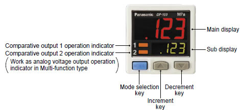
Part description
|
Wiring
- Make sure that the power supply is off while wiring.
- Verify that the supply voltage variation is within the rating.。
- If power is supplied from a commercial switching regulator, ensure that the frame ground (F.G.) terminal of the power supply is connected to an actual ground.
- In case noise generating equipment (switching regulator, inverter motor, etc.) is used in the vicinity of this sensor, connect the frame ground (F.G.) terminal of the equipment to an actual ground.
- Do not run the wires together with high-voltage lines or power lines or put them in the same raceway. This can cause malfunction due to induction.
- Incorrect wiring will cause problems with operation.
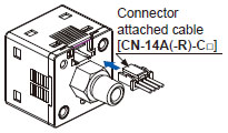
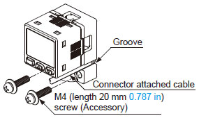
Connection
- Do not apply stress directly to the connection cable leader or to the connector.
|
Conditions in use for CE and UKCA conformity
- TThe DP-100 series is a CE and UKCA conformity product complying with EMC Directive. The harmonized standard with regard to immunity that applies to this product is EN 61000-6-2 and the following condition must be met to conform to that standard.
[Condition]
・The line to connect with this sensor should be less than 30 m 98.425 ft.
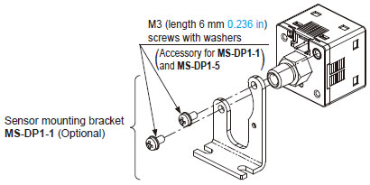
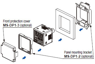
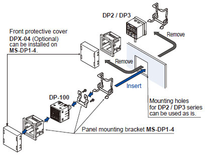
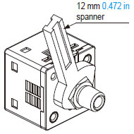
Mounting
|
|
|
|
|
|
|
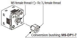
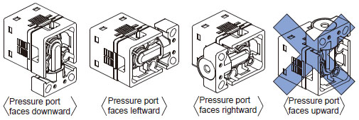
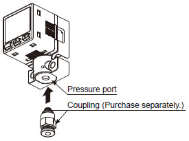
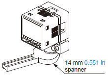
Piping
|
|

|
|
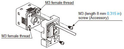
Flat attachment
- Make sure to mount MS-DP1-F□ with the sensor properly. If it is not mounted properly, air leakage may occur.
- Take care that the excessive mounting and dismounting of this product may cause deterioration of the O-ring.
- If you touch the O-ring of MS-DP1-F□, or any scratch or dust, etc. is attached to it, air leakage may occur and the sensing performance may deteriorate. Take sufficient care when using and storing MS-DP1-F□.
Others
- This product has been developed / produced for industrial use.
- Use within the rated pressure range.
- Do not apply pressure exceeding the pressure withstandability value. The diaphragm will get damaged and correct operation shall not be maintained.
- Do not use during the initial transient time (0.5 sec. approx.) after the power supply is switched on.
- Avoid dust, dirt, and steam.
- Take care that the sensor does not come in direct contact with water, oil, grease, or organic solvents, such as, thinner, etc.
- Do not insert wires, etc., into the pressure port. The diaphragm will get damaged and correct operation shall not be maintained.
- Do not operate the keys with pointed or sharp objects.
RUN mode
- This is the normal operating mode.
| Setting item | Description |
|---|---|
| Threshold value setting | The threshold values for ON / OFF operation can be changed directly by pressing the increment key (UP) and the decrement key (DOWN). |
| Zero-adjustment function | This forces the pressure value display to be reset to zero when the pressure port is open on the atmospheric pressure side. |
| Key lock function | Stops key operations from being accepted. |
| Peak hold / bottom hold function | Displays the peak value and bottom value for fluctuating pressure. The peak value appears in the main display, and the bottom value appears in the sub display. |
MENU SETTING mode
- If the mode selection key is pressed and held for 2 seconds in RUN mode, the mode will switch to MENU SETTING mode.
- If the mode selection key is pressed while a setting is being made, the mode will switch to RUN mode. In this case, the settings that have been changed will be entered.
| Setting item | Description |
|---|---|
| Comparative output 1 output mode setting |
Sets the output mode for comparative output 1. |
| Comparative output 2 output mode setting (standard type only) |
Sets the output mode for comparative output 2. |
| Analog output / external input switching (multi-function type only) |
Allows switching between analog voltage output / analog current output, and auto-reference input / remote zero-adjust-ment input. |
| NO / NC switching | Sets normally open (NO) or normally closed (NC). |
| Response time setting | Sets the response time. The response time can be selected from 2.5 ms, 5 ms, 10 ms, 25 ms, 50 ms, 100 ms, 250 ms, 500 ms, 1,000 ms and 5,000 ms. |
| Display color switching for main display |
Allows the color for the main display to be changed. The colors can be set to ‘red / green’ or ‘green / red' to correspond to ON / OFF output, or it can be fixed at ‘red’ or ‘green’ all the time. |
| Unit switching | Pressure unit can be changed. |
PRO mode
- If the mode selection key is pressed and held for 5 seconds in RUN mode, the mode will switch to PRO mode.
- If the mode selection key is pressed while a setting is being made, the mode will switch to RUN mode. In this case, the settings that have been changed will be entered.
| Setting item | Description |
|---|---|
| Sub display switching | Changes the information in the sub display during RUN mode operation to the desired alphanumeric display. |
| Display refresh rate switching |
Changes the display refresh rate for the pressure value displayed in the main display. |
| Hysteresis fix value switching |
Sets the hysteresis for EASY mode and window comparator mode. (8 steps) |
| Linked display color switching (standard type only) |
Allows the display color for the main display to be switched in line with the output operation for comparative output 1 or comparative output 2. |
| ECO mode setting | Allows power consumption to be reduced by dimming the display or turning it off. |
| Setting check code | Allows the setting details to be checked via codes. |
| Setting copy mode | Allows the setting details for the master sensor to be copied to slave sensors. |
| Reset setting | Resets the settings to the factory settings. |
|
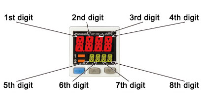
| Code | 1st digit | 2nd digit | 3rd digit | 4th digit | ||||
|---|---|---|---|---|---|---|---|---|
| Standard type | Multi-function type | Standard type only | ||||||
| Comparative output 1 output mode |
NO/NC switching |
Comparative output 2 output mode |
NO/NC switching |
Analog voltage output / External input |
Threshold value display |
Display color for main display | Display color linking | |
| 0 | EASY | NO | OFF | OFF | Analog voltage output |
P-1, Lo-1 | Red when ON |
Comparative output 1 |
| 1 | NC | EASY | NO | Auto reference |
Hi-1 | Comparative output 2 |
||
| 2 | Hysteresis | NO | NC | Remote zero-adjustment |
P-2, Lo-2 | Green when ON |
Comparative output 1 |
|
| 3 | NC | Hysteresis | NO | Analog current output |
Hi-2 | Comparative output 2 |
||
| 4 | Window comparator |
NO | NC | - | ADJ. | Always red |
Comparative output 1 |
|
| 5 | NC | Window comparator |
NO | - | - | Comparative output 2 |
||
| 6 | - | - | NC | - | - | Always green |
Comparative output 1 |
|
| 7 | - | - | - | - | - | - | Comparative output 2 |
|
| コード | 5th digit | 6th digit | 7th digit | 8th digit |
|---|---|---|---|---|
| Response time | Unit switching | Display refresh rate | ECO mode | |
| 0 | 2.5ms | MPa | 250ms | OFF |
| 1 | 5ms | kPa | 500ms | STD |
| 2 | 10ms | kgf/cm2 | 1,000ms | FULL |
| 3 | 25ms | bar | - | - |
| 4 | 50ms | psi | - | - |
| 5 | 100ms | mmHg | - | - |
| 6 | 250ms | inchHg | - | - |
| 7 | 500ms | - | - | - |
| 8 | 1,000ms | - | - | - |
| 9 | 5,000ms | - | - | - |
BY EMAIL
- U.S.A.
- +1-800-344-2112
- Europe
- +49-89-45354-1000
- China
- +86-10-59255988
- Singapore
- +65-6299-9181


Requests to customers (Automation Control Components & Industrial Device) [Excluding specific product]
Requests to customers (Automation Control Components & Industrial Device) [For specific product]
Requests to customers (FA Sensors & Components [Excluding motors])
Requests to customers (Dedicated to industrial motors)
- COMPONENTS & DEVICES
- FA SENSORS & COMPONENTS
- Fiber Sensors
- Photoelectric Sensors / Laser Sensors
- Micro Photoelectric Sensors
- Light Curtains / Safety Components
- Area Sensors
- Inductive Proximity Sensors
- Particular Use Sensors
- Sensor Options
- Wire-Saving Systems
- Programmable Controllers / Interface Terminal
- Human Machine Interface
- Pressure Sensors / Flow Sensors
- Measurement Sensors
- Static Control Devices
- Laser Markers / 2D Code Readers
- Machine Vision System
- Energy Management Solutions
- Timers / Counters / FA Components
- MOTORS
![]()