[System Maintenance Notice]
Due to ongoing system maintenance, the site search and specification search functions are temporarily unavailable. We apologize for any inconvenience this may cause and appreciate your understanding.
【Notification of Manufacturer Change for Panasonic Industrial Devices SUNX Products and Panasonic Industrial Devices SUNX Tatsuno Products】
From April 1, 2024, the terms "Panasonic Industrial Devices SUNX Co., Ltd." and "Panasonic Industrial Devices SUNX Tatsuno Co., Ltd."
in this page and in the manuals and other documents to be downloaded will all be replaced with "Panasonic Industry Co., Ltd." and applied accordingly.
Head-separated Dual display Digital Pressure Sensor [For gas & liquid] DPC-L100 / DPH-L100
I/O Circuit and Wiring diagrams
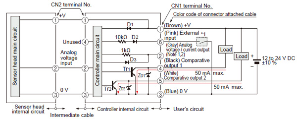
DPC-L101
I/O circuit diagram
Notes:
| 1) |
Set the output load resistance during analog current output to 250 Ω (max.). |
| 2) |
Note that a voltage of 5 V or higher is generated during analog current output. |
| Symbols・・・ |
D1 to D3 : Reverse supply polarity protection diode
ZD1, ZD2 : Surge absorption zener diode
Tr1, Tr2 : NPN output transistor |
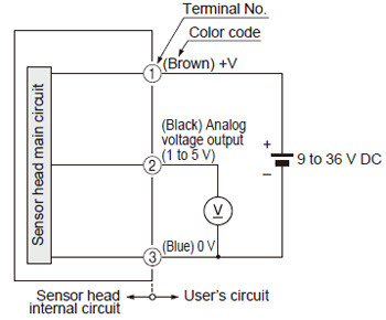
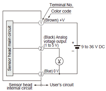
| For independent use of sensor head |
Notes:
| 1) |
When the sensor head is used independently, devices connected to the analog output must have an input impedance set at 10 kΩ or more and load capacity 1,000 pF or less. |
| 2) |
No short-circuit protection circuit is provided for analog voltage output. Do not connect directly to a power supply. |
| 3) |
The pressure port and internal circuitry are connected by a capacitor. Do not apply voltage in excess of the specifications’ dielectric strength between the pressure port and wiring. |
| 4) |
The transparent tube attached to the cable is not used and should be cut off at the base. |
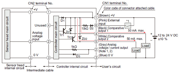
DPC-L101-P
I/O circuit diagram
Notes:
| 1) |
Set the output load resistance during analog current output to 250 Ω (max.). |
| 2) |
Note that a voltage of 5 V or higher is generated during analog current output. |
| Symbols・・・ |
D1 to D3 : Reverse supply polarity protection diode
ZD1, ZD2 : Surge absorption zener diode
Tr1, Tr2 : PNP output transistor |
| For independent use of sensor head |
Notes:
| 1) |
When the sensor head is used independently, devices connected to the analog output must have an input impedance set at 10 kΩ or more and load capacity 1,000 pF or less. |
| 2) |
No short-circuit protection circuit is provided for analog voltage output. Do not connect directly to a power supply. |
| 3) |
The pressure port and internal circuitry are connected by a capacitor.
Do not apply voltage in excess of the specifications’ dielectric strength between the pressure port and wiring. |
| 4) |
The transparent tube attached to the cable is not used and should be cut off at the base. |
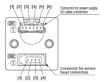
Terminal arrangement diagram
|
|
| Connector for power supply I/O cable (CN1) |
[1] +V
[2] Analog voltage / current output
[3] 0 V
[4] Comparative output 1
[5] Comparative output 2
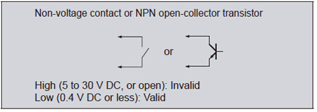
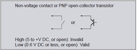
[6] External input
(auto-reference function / remote zero-adjustment function / current value hold function)
| Connector for sensor head (CN2) |
[1] Sensor head supply voltage
[2] Analog voltage input
[3] 0 V
[4] Unused
|
Return to top
Return to top

 Business
> Industrial Devices
> Automation Controls Top
> FA Sensors & Components
> Pressure Sensors / Flow Sensors
> Pressure Sensors / Flow Sensors
> Head-separated Dual display Digital Pressure Sensor [For gas & liquid] DPC-L100 / DPH-L100
> I/O Circuit and Wiring diagrams
Business
> Industrial Devices
> Automation Controls Top
> FA Sensors & Components
> Pressure Sensors / Flow Sensors
> Pressure Sensors / Flow Sensors
> Head-separated Dual display Digital Pressure Sensor [For gas & liquid] DPC-L100 / DPH-L100
> I/O Circuit and Wiring diagrams