[System Maintenance Notice]
Due to ongoing system maintenance, the site search and specification search functions are temporarily unavailable. We apologize for any inconvenience this may cause and appreciate your understanding.
【Notification of Manufacturer Change for Panasonic Industrial Devices SUNX Products and Panasonic Industrial Devices SUNX Tatsuno Products】
From April 1, 2024, the terms "Panasonic Industrial Devices SUNX Co., Ltd." and "Panasonic Industrial Devices SUNX Tatsuno Co., Ltd."
in this page and in the manuals and other documents to be downloaded will all be replaced with "Panasonic Industry Co., Ltd." and applied accordingly.
Integrated Display Type Digital Flow Sensor FM-200 (Discontinued Products)
We are sorry, the products have been discontinued. Please refer to the details of the discontinued products and the recommended substitutes list below.
 |
July 31, 2022 |
|
|
I/O Circuit and Wiring diagrams
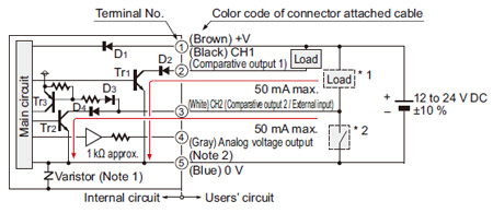
FM-2□
I/O circuit diagram
Notes:
| 1) |
As for the aluminum body type, varistor (clamping voltage approx. 40 V) is connected between the internal power circuit and the metal body to prevent breakdown of the sensor. Connect the metal body to +V of power supply or to frame ground (F.G.) of a device that is connected to 0 V. High potential and insulation resistance tests between the internal power circuit and the metal body must not be done. |
| 2) |
Short-circuit protection is not incorporated into the analog voltage output. Do not connect the power supply or capacitive load directly to the analog voltage output. |
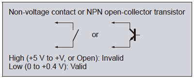
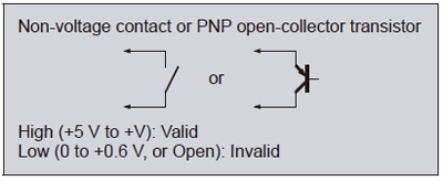
| Symbols・・・ |
D1 to D4 : Reverse supply polarity protection diode
Tr1,Tr2 : NPN output transistor
Tr3 : PNP input transistor |
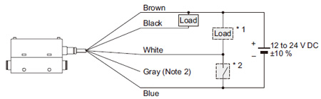
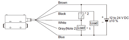
Wiring diagram
*1: When using CH2 as a comparative output 2
*2: When using CH2 as an external input
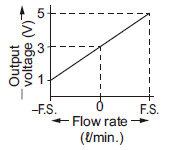
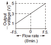
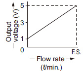
Analog voltage output
<Bi-direction detection> |
|---|
 |
|
|
<One-side detection> |
|---|
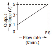 |
|
|
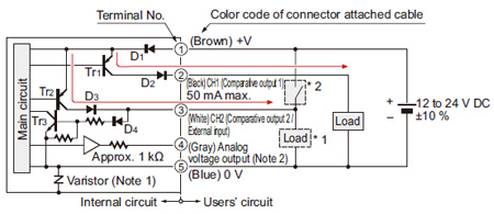
FM-2□-P
I/O circuit diagram
Notes:
| 1) |
As for the aluminum body type, varistor (clamping voltage approx. 40 V) is connected between the internal power circuit and the metal body to prevent breakdown of the sensor. Connect the metal body to +V of power supply or to frame ground (F.G.) of a device that is connected to 0 V. High potential and insulation resistance tests between the internal power circuit and the metal body must not be done. |
| 2) |
Short-circuit protection is not incorporated into the analog voltage output. Do not connect the power supply or capacitive load directly to the analog voltage output. |
| Symbols・・・ |
D1 to D4 : Reverse supply polarity protection diode
Tr1,Tr2 : PNP output transistor
Tr3 : NPN input transistor |
Wiring diagram
*1: When using CH2 as a comparative output 2
*2: When using CH2 as an external input
Analog voltage output
<Bi-direction detection> |
|---|
 |
|
|
<One-side detection> |
|---|
 |
|
|
Return to top
Return to top

 Business
> Industrial Devices
> Automation Controls Top
> FA Sensors & Components
> Pressure Sensors / Flow Sensors
> Pressure Sensors / Flow Sensors
> Integrated Display Type Digital Flow Sensor FM-200(Discontinued Products)
> I/O Circuit and Wiring diagrams
Business
> Industrial Devices
> Automation Controls Top
> FA Sensors & Components
> Pressure Sensors / Flow Sensors
> Pressure Sensors / Flow Sensors
> Integrated Display Type Digital Flow Sensor FM-200(Discontinued Products)
> I/O Circuit and Wiring diagrams