[System Maintenance Notice]
Due to ongoing system maintenance, the site search and specification search functions are temporarily unavailable. We apologize for any inconvenience this may cause and appreciate your understanding.
【Notification of Manufacturer Change for Panasonic Industrial Devices SUNX Products and Panasonic Industrial Devices SUNX Tatsuno Products】
From April 1, 2024, the terms "Panasonic Industrial Devices SUNX Co., Ltd." and "Panasonic Industrial Devices SUNX Tatsuno Co., Ltd."
in this page and in the manuals and other documents to be downloaded will all be replaced with "Panasonic Industry Co., Ltd." and applied accordingly.
Digital Fiber Sensor FX-410
Cautions For Use
- Never use this product as a sensing device for personnel protection.
- In case of using sensing devices for personnel protection, use products which meet laws and standards, such as OSHA, ANSI or IEC etc., for personnel protection applicable in each region or country.
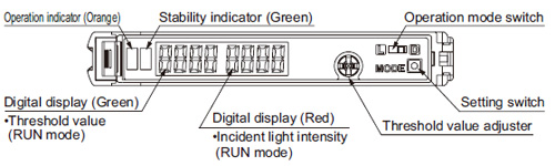
Part description
Wiring
- Make sure that the power supply is off while wiring.
- Verify that the supply voltage variation is within the rating.
- Take care that if a voltage exceeding the rated range is applied, or if an AC power supply is directly connected, the product may get burnt or damaged.
- In case noise generating equipment (switching regulator, inverter motor, etc.) is used in the vicinity of this product, connect the frame ground (F.G.) terminal of the equipment to an actual ground.
- If power is supplied from a commercial switching regulator, ensure that the frame ground (F.G.) terminal of the power supply is connected to an actual ground.
- Take care that short circuit of the load wrong wiring may burn or damage the product.
- Do not run the wires together with high-voltage lines or power lines or put them in the same raceway. This can cause malfunction due to induction.
- Extension up to total 100 m 328.084 ft (if 5 to 8 units are connected in cascade: 50 m 164.042 ft, if 9 to 16 units are connected in cascade: 20 m 65.617 ft) is possible with 0.3 mm2, or more, cable. However, in order to reduce noise, make the wiring as short as possible.
- Take care that cable extension increases the residual voltage.
Mounting
| ・ |
Make sure that the power supply is off while connecting / disconnecting the amplifiers and the quick-connection cables. |
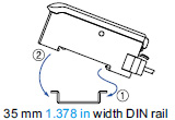
| How to mount the amplifier |
| ① |
Fit the rear part of the mounting section of the amplifier on a width DIN rail. |
| ② |
Press down the rear part of the mounting section of the unit on the width DIN rail and fit the front part of the mounting section to the DIN rail. |
|
|
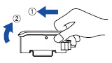
| How to remove the amplifier |
| ① |
Push the amplifier forward. |
| ② |
Lift up the front part of the amplifier to remove it. |
|
|
| Note: |
Take care that if the front part is lifted without pushing the amplifier forward, the hook on the rear portion of the mounting section is likely to break. |
| ・ |
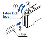
Insert the fiber into the amplifier after attaching the attachment. Refer to the "Instruction Manual" included with the fiber for details. |
| ① |
Push the fiber lock lever down. |
| ② |
Slowly insert the fiber into the insertion slot until it stops. (Note 1) |
| ③ |
Push the fiber lock lever back up until it stops. |
|
|
Notes:
| 1) |
Note that if the fiber is not fully inserted, the sensing distance will decrease. Also note that the bending-resistant fiber may bend during insertion. |
| 2) |
In case of coaxial reflective type fibers, mount the central fiber (single-core) to the emitter part and the peripheral fiber (multi-core) to the receiver. Note that sensing precision will deteriorate when done in reverse. |
| ・ |
Make sure that the power supply is off while adding or removing the amplifiers. |
| ・ |
Make sure to check the allowable ambient temperature, as it depends on the number of amplifiers connected in cascade. |
| ・ |
In case two, or more, amplifiers are connected in cascade, make sure to mount them on a DIN rail. |
| ・ |
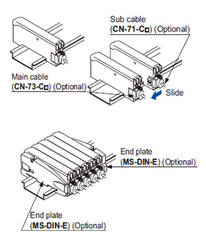
When the amplifiers move on the DIN rail depending on the attaching condition or the amplifiers are mounted close to each other in cascade, fit them between the optional end plates (MS-DIN-E) mounted at the two ends. |
| ・ |
Up to maximum 15 amplifiers can be added (total 16 amplifiers connected in cascade.) |
| ・ |
When connecting more than two amplifiers in cascade, use the sub cable (CN-71-C□) as the quickconnection cable for the second amplifier onwards. |
| ・ |
When connecting amplifiers not close to each other in parallel, be sure to mount the optional end plate (MS-DIN-E) at both sides of each amplifier or affix the communication window seal of the optional fiber amplifier protection seal (FX-MB1) to the communication windows. For details, refer to the instruction manual enclosed with the FX-MB1. |
| ・ |
When the different LED (red / blue / green) types are connected in cascade, mount the identical models together. |
| ・ |
When this product is used with the other digital fiber amplifiers, be sure to place this product to the left most position (When you look from the connector side). If this product is not placed to the leftmost position, this product may not operate properly. |
| ① |
Mount the amplifiers, one by one, on the DIN rail. |
| ② |
Slide the amplifiers next to each other, and connect the quick-connection cables. |
| ③ |
Mount the optional end plates (MS-DIN-E) at both the ends to hold the amplifiers between their flat sides. |
| ④ |
Tighten the screws to fix the end plates. |
|
|
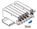
| ① |
Loosen the screws of the end plates. |
| ② |
Remove the end plates. |
| ③ |
Slide the amplifiers and remove them one by one. |
|
|
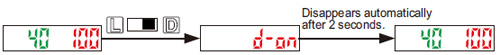
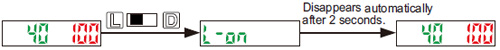
Switching output operation
- The operation selection switch can be used to display different output operations (L-ON / D-ON) on the digital display.
| When set to Dark-ON (D-ON) |
| When set to Light-ON (L-ON) |
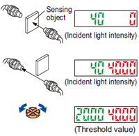
Threshold value (sensitivity) adjustment
| ① |
Check the incident light intensity [in the digital display (red)] when a sensing object is placed in the sensing position. |
| ② |
Check the incident light intensity [in the digital display (red)] when the sensing object is removed from the sensing position. |
| ③ |
Turn the threshold value adjuster to the threshold value [in the digital display (green)] that is the value in between ① and ②. (The threshold value is automatically written to the EEPROM.) |
|
|
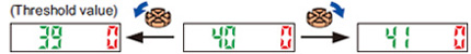
| Threshold value setting method |
- When the threshold value adjuster is turned clockwise, the threshold value increases. When the threshold value adjuster is turned counterclockwise, the threshold value decreases.
| ・ |
If there is a sufficient level of margin in the incident light intensity, the stability indicator (green) will light up. |
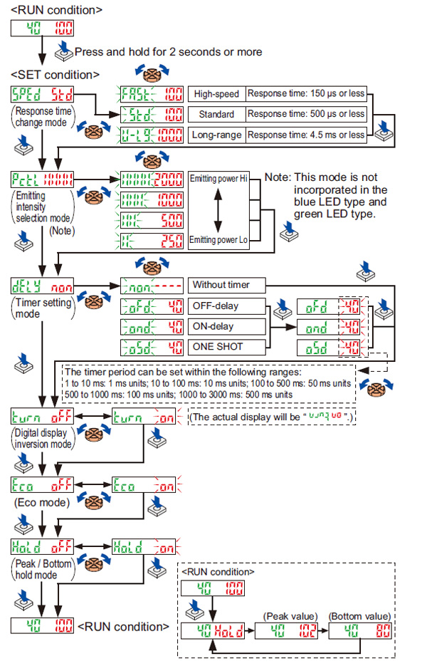
Mode selection
- When the setting switch is pressed and held for 2 sec. or more, “SET” mode (mode setting screen) is activated.
- If the setting switch is pressed while in “SET” mode, the mode will change.
- If the threshold value adjuster is turned while a mode is active, the setting item will change and blink.
- When the setting switch is pressed at the item you would like to set, it blinks 3 times and then the setting is confirmed and the mode switches to the next mode.
- If the setting switch is pressed and held for 2 sec. or more or do not press any key for 15 sec. while “SET” mode is active, the mode will switch automatically to “RUN” mode.
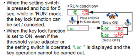
Key lock function
| Note: |
Although the display changes to the indication of ‘SET’ condition 2 sec. after pressing the setting switch, keep pressing the switch. Furthermore, the sensor does not go into the key lock setting from ‘SET’ condition. |
Factory setting
Error display indicator readings
| Display |
Error description |
Measures |
 |
The load has short-circuited and excess current is flowing. |
Turn off the power, then check the load. |
 |
Communication error has occurred at time of connection. |
Check if the mounted amplifiers are in close contact with each other. |
Others
- This product has been developed / produced for industrial use only.
- Do not use during the initial transient time (0.5 sec.) after the power supply is switched on.
- This sensor is suitable for indoor use only.
- Do not use this sensor in places having excessive vapor, dust, etc., or where it may come in contact with corrosive gas.
- Take care that the sensor does not come in direct contact with oil, grease, organic solvents, such as, thinner etc., or strong acid, and alkaline.
- This sensor cannot be used in an environment containing inflammable or explosive gases.
- Never disassemble or modify the sensor.
- The changes to the settings are written to the EEPROM, but because the EEPROM has a limited service life, you should avoid changing the settings any more than 1 million times.
Return to top
Return to top

 Business
> Industrial Devices
> Automation Controls Top
> FA Sensors & Components
> Sensors
> Fiber Sensors
> Digital Fiber Sensor FX-410
> Cautions For Use
Business
> Industrial Devices
> Automation Controls Top
> FA Sensors & Components
> Sensors
> Fiber Sensors
> Digital Fiber Sensor FX-410
> Cautions For Use