【Notification of Manufacturer Change for Panasonic Industrial Devices SUNX Products and Panasonic Industrial Devices SUNX Tatsuno Products】
From April 1, 2024, the terms "Panasonic Industrial Devices SUNX Co., Ltd." and "Panasonic Industrial Devices SUNX Tatsuno Co., Ltd."
in this page and in the manuals and other documents to be downloaded will all be replaced with "Panasonic Industry Co., Ltd." and applied accordingly.
Digital Fiber Sensor FX-500 Ver.2
I/O Circuit and Wiring diagrams
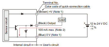
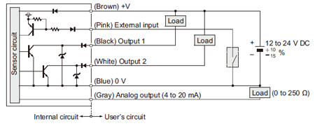
FX-501
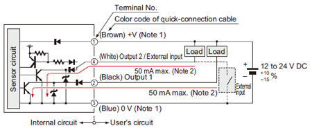
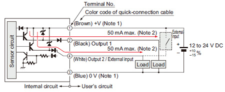
I/O circuit diagram
Notes:
| 1) |
The quick-connection sub cable does not have +V (brown) and 0 V (blue). The power is supplied from the connector of the main cable. |
| 2) |
50 mA max., if five amplifiers or more, are connected together. |
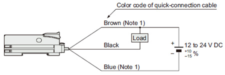
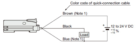
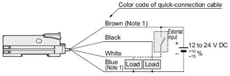
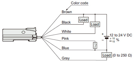
Wiring diagram
| Note: |
The quick-connection sub cable does not have a brown and a blue lead wire. |
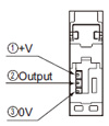
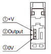
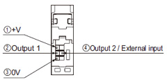
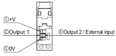
Terminal arrangement diagram
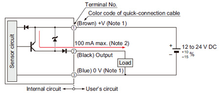
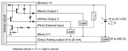
FX-501P
I/O circuit diagram
Notes:
| 1) |
The quick-connection sub cable does not have +V (brown) and 0 V (blue). The power is supplied from the connector of the main cable. |
| 2) |
50 mA max., if five amplifiers or more, are connected together. |
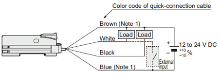
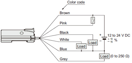
Wiring diagram
| Note: |
The quick-connection sub cable does not have a brown and a blue lead wire. |
Terminal arrangement diagram
FX-502
I/O circuit diagram
Notes:
| 1) |
The quick-connection sub cable does not have +V (brown) and 0 V (blue). The power is supplied from the connector of the main cable. |
| 2) |
25 mA max., if five amplifiers or more, are connected together. |
Wiring diagram
| Note: |
The quick-connection sub cable does not have a brown and a blue lead wire. |
Terminal arrangement diagram
FX-502P
I/O circuit diagram
Notes:
| 1) |
The quick-connection sub cable does not have +V (brown) and 0 V (blue). The power is supplied from the connector of the main cable. |
| 2) |
25 mA max., if five amplifiers or more, are connected together. |
Wiring diagram
| Note: |
The quick-connection sub cable does not have a brown and a blue lead wire. |
Terminal arrangement diagram
FX-505-C2
FX-505P-C2
Return to top
Return to top

 Business
> Industrial Devices
> Automation Controls Top
> FA Sensors & Components
> Sensors
> Fiber Sensors
> Digital Fiber Sensor FX-500 Ver.2
> I/O Circuit and Wiring diagrams
Business
> Industrial Devices
> Automation Controls Top
> FA Sensors & Components
> Sensors
> Fiber Sensors
> Digital Fiber Sensor FX-500 Ver.2
> I/O Circuit and Wiring diagrams