[System Maintenance Notice]
Due to ongoing system maintenance, the site search and specification search functions are temporarily unavailable. We apologize for any inconvenience this may cause and appreciate your understanding.
【Notification of Manufacturer Change for Panasonic Industrial Devices SUNX Products and Panasonic Industrial Devices SUNX Tatsuno Products】
From April 1, 2024, the terms "Panasonic Industrial Devices SUNX Co., Ltd." and "Panasonic Industrial Devices SUNX Tatsuno Co., Ltd."
in this page and in the manuals and other documents to be downloaded will all be replaced with "Panasonic Industry Co., Ltd." and applied accordingly.
Small U-shaped Micro Photoelectric Sensor[Amplifier Built-in] PM-44/PM-54 (Discontinued Products)
We are sorry, the products have been discontinued. Please refer to the details of the discontinued products and the recommended substitutes list below.
 |
March 31, 2017 |
|
|
Cautions For Use
- Never use this product as a sensing device for personnel protection.
- In case of using sensing devices for personnel protection, use products which meet laws and standards, such as OSHA, ANSI or IEC etc., for personnel protection applicable in each region or country.
- Make sure to connect terminals correctly as the sensor does not incorporate a reverse polarity protection circuit.
Further, the output is not incorporated with a short-circuit protection circuit. Do not connect it directly to a power supply or a capacitive load.
Faulty wiring may result in damage.
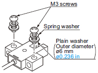
Mounting
- When fixing the sensor with screws, use M3 screws and the tightening torque should not exceed the values given below.
Further, use small, round type plain washers (ø6 mm ø0.236 in).
| Model No. |
Tightening torque |
| PM-□44(P) |
0.5 N·m |
| PM-□54(P) |
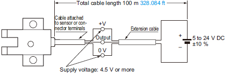
Cable extension
- Cable extension is possible up to an overall length of 100 m 328.084 ft with a 0.3 mm2, or more, cable.
However, since a voltage drop shall occur due to the cable extension, ensure that the power supply voltage at the end of the cable attached to the sensor or at the sensor terminals is within the rating.
But, when the overall cable length, including the cable attached to the sensor, is as given below, there is no need to confirm the voltage.
Conductor cross-section
area of
extension cable |
Total cable length |
| 0.08 to 0.1 mm2 |
Up to 5 m 16.404 ft |
| 0.2 mm2 |
Up to 10 m 32.808 ft |
| 0.3 mm2 |
Up to 20 m 65.617 ft |
Others
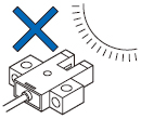
- Since the sensor is intended for use inside machines, no special countermeasures have been taken against extraneous light. Take care that extraneous light is not directly incident on the beam receiving section.
- Do not use during the initial transient time (50 ms) after the power supply is switched on.
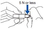
Cautions in plugging or unplugging a connector
- Do not plug or unplug a connector more than 10 times.
- Be sure not to give stress more than 5 N to a terminal of both a connector and a sensor.
If you do not follow the above cautions, it will cause a poor contact.
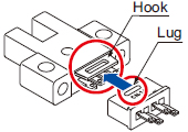
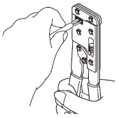
| Procedures of plugging or unplugging a connector |
(1)Insert a connector straight into a sensor until the connector lug is locked by the sensor hook. |
|
(2)When unplugging, give as much stress as a connector lug can be relieved from a hook. Then unplug it. |
|
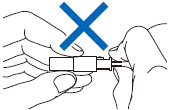
| Caution: |
Be sure to hold a connector when plugging or unplugging it. Do not hold a terminal or a cable when plugging or unplugging the connector.
Otherwise, it will cause a poor contact.
 |
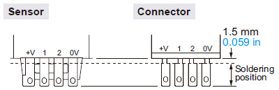
Soldering (Both connector CN-14 and sensor)
- If soldering is done directly on the terminals, strictly adhere to the conditions given below.
| Soldering temperature |
260 ℃ 500 ℉ or less |
| Soldering time |
3 sec. or less |
| Soldering position |
Refer to the below figure |
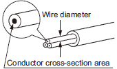
Crimping of hook-up connectors CN-14H and CN-14H-2
| Item |
CN-14H |
CN-14H-2 |
| Conductor cross-section area |
0.08 to 0.2 mm2
(AWG28 to AWG24) |
0.18 to 0.22 mm2
(AWG25 to AWG24) |
| Wire diameter |
ø0.7 to ø1.2 mm
ø0.028 to ø0.047 in |
ø1.2 to ø1.52 mm
ø0.047 to ø0.060 in |
| Wire insulation material |
Vinyl chloride or soft polyethylene |
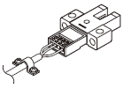
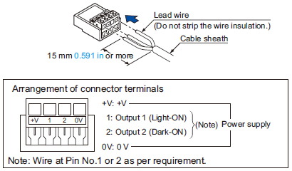
| (1) |
Strip the cable sheath 15 mm 0.591 in, or more, and insert the wires into the connector insertion holes till the wire tips reach the end. |
|
 |
|
| (2) |
Crimp with the exclusive hook-up pliers CN-HP. |
|
 |
Notes:
| 1) |
When attaching or detaching the connector fitted with a cable, make sure to hold the connector firmly before proceeding. |
| 2) |
After crimping, do not pull on the cable. |
|
|
| Caution: |
Make sure to use the exclusive hook-up pliers CN-HP. Commercially available pliers cannot be used. |
- Prior to using the sensor, affix the cable in a way as to avoid direct stress on the crimped part.
Return to top
Return to top

 Business
> Industrial Devices
> Automation Controls Top
> FA Sensors & Components
> Sensors
> Micro Photoelectric Sensors
> Small U-shaped Micro Photoelectric Sensor[Amplifier Built-in] PM-44/PM-54(Discontinued Products)
> Cautions For Use
Business
> Industrial Devices
> Automation Controls Top
> FA Sensors & Components
> Sensors
> Micro Photoelectric Sensors
> Small U-shaped Micro Photoelectric Sensor[Amplifier Built-in] PM-44/PM-54(Discontinued Products)
> Cautions For Use