[System Maintenance Notice]
Due to ongoing system maintenance, the site search and specification search functions are temporarily unavailable. We apologize for any inconvenience this may cause and appreciate your understanding.
【Notification of Manufacturer Change for Panasonic Industrial Devices SUNX Products and Panasonic Industrial Devices SUNX Tatsuno Products】
From April 1, 2024, the terms "Panasonic Industrial Devices SUNX Co., Ltd." and "Panasonic Industrial Devices SUNX Tatsuno Co., Ltd."
in this page and in the manuals and other documents to be downloaded will all be replaced with "Panasonic Industry Co., Ltd." and applied accordingly.

 Business
> Industrial Devices
> Automation Controls Top
> FA Sensors & Components
> Sensors
> Light Curtains / Safety Components
> Safety Light Curtain Type 4 SF4B Ver.2(Discontinued Products)
> Cautions For Use
Business
> Industrial Devices
> Automation Controls Top
> FA Sensors & Components
> Sensors
> Light Curtains / Safety Components
> Safety Light Curtain Type 4 SF4B Ver.2(Discontinued Products)
> Cautions For Use
Safety Light Curtain Type 4 SF4B Ver.2 (Discontinued Products)
|
We are sorry, the products have been discontinued. Please refer to the details of the discontinued products and the recommended substitutes list below.
|
Cautions For Use
Interlock function
- The selection of manual reset / automatic reset is available by applying the interlock input wiring. The interlock becomes available by selecting manual reset.
(Refer to the SF4B / SF4B-G instruction manual for details.)
Emission halt function
- This function stops the emission process of the emitter.
You can select whether emission is on or halted by means of the connection status for the emission halt input / reset input wire (pink). - During emission halt, the control outputs (OSSD 1, OSSD 2) become OFF status.
- By using this function, malfunction due to extraneous noise or abnormality in the control outputs (OSSD 1, OSSD 2) and the auxiliary output can be determined even from the machinery side.
- Normal operation is restored when the emission halt input / reset input wire (pink) is connected to 0 V or +V.
(Refer to the SF4B / SF4B-G instruction manual for details.)
Auxiliary output (Non-safety output)
- This safety light curtain incorporates the auxiliary output (yellowgreen / black) for the non-safety output. The auxiliary output is incorporated with the emitter.
(Refer to the SF4B / SF4B-G instruction manual for details.)
External device monitoring function
- This is the function for checking whether the external safety relay connected to the control outputs (OSSD 1, OSSD 2) perform normally in accordance with the control outputs (OSSD 1, OSSD 2) or not. Monitor the contacting point “b” of the external safety relay, and if any abnormality such as deposit of the contacting point, etc. is detected, change the status of the safety light curtain into lockout one, and turn OFF the control outputs (OSSD 1, OSSD 2). (Refer to the SF4B / SF4B-G instruction manual for details.)
Muting function
- This function turns the safety function of this safety light curtain into disabled temporarily. When the control outputs (OSSD 1, OSSD 2) are ON, this function is available for passing the workpiece through the sensing area of the safety light curtain without stopping the machinery.
The muting function becomes valid when all the conditions listed below are satisfied.
However, this function connot be used with the SF4B-□-03.
①The control outputs (OSSD 1, OSSD 2) shall be ON.
②The incandescent lamp with 3 to 10 W shall be connected to the muting lamp output (red).
③The output of the muting sensors A and B shall be changed from OFF (open) to ON. At this time, the time difference occurred by changing the output of the muting sensors A and B into ON status shall be within 0.03 to 3 sec. - The following devices, photoelectric sensor with semiconductor output, inductive proximity sensor, position switch on N.O. (Normally open) contact, etc.
are available for applying to the muting sensor. - In case of using the muting function, please order 12-core cable.
(Refer to the SF4B / SF4B-G instruction manual for details.)
Override function
- This function sets the safety function of this safety light curtain enabled forcibly.
When using the muting function, the override function can be used to start the machinery at times such as when the control outputs (OSSD 1 and OSSD 2) are OFF or when the muting sensors are ON when the line is to be started.
The override function becomes valid when all the conditions listed below are satisfied. However, this function cannot be used with the SF4B-□-03<V2>.
(Refer to the SF4B / SF4B-G instruction manual for details.)
Series connection
| Connectable up to 3 sets of safety light curtains (however, 192 beam channels max.) |
(Refer to the SF4B / SF4B-G instruction manual for details.)
Parallel connection
| Connectable up to 3 sets of safety light cartains |
(Refer to the SF4B / SF4B-G instruction manual for details.)
Series and parallel mixed connection
| Connectable up to 3 sets of safety light curtains (however, 192 beam channels max.) |
(Refer to the SF4B / SF4B-G instruction manual for details.)
Wiring
- Refer to the applicable regulations for the region where this device is to be used when setting up the device. In addition, make sure that all necessary measures are taken to prevent possible dangerous operating errors resulting from earth faults.
- Make sure to carry out the wiring in the power supply off condition.
- Verify that the supply voltage variation is within the rating.
- If power is supplied from a commercial switching regulator, ensure that the frame ground (F.G.) terminal of the power supply is connected to an actual ground.
- In case noise generating equipment (switching regulator, inverter motor, etc.) is used in the vicinity of this sensor, connect the frame ground (F.G.) terminal of the equipment to an actual ground.
- Do not run the wires together with high-voltage lines or power lines or put them in the same raceway. This can cause malfunction due to induction.
Others
- This device has been developed / produced for industrial use only.
- Do not use during the initial transient time (2 sec.) after the power supply is switched on.
- Avoid dust, dirt and steam.
- Take care that the safety light curtain does not come in direct contact with water, oil, grease, or organic solvents, such as, thinner, etc.
- Take care that the safety light curtain is not directly exposed to fluorescent light from a rapid-starter lamp or a high frequency lighting device, as it may affect the sensing erformance.
- When this device is used in the “PSDI mode”, an appropriate control circuit must be configured between this device and the machinery. For details, be sure to refer to the standards or regulations applicable in each region or country.
- To use device in the U.S.A., refer to OSHA 1910. 212 and OSHA 1910. 217 for installation, and in Europe, refer to EN ISO 13855 as well. Observe your national and local requirements before installing this product.
| ・ | This catalog is a guide to select a suitable product. Be sure to read instruction manual prior to its use. |
|---|---|
| ・ | Both emitter and receiver are adjusted before shipment, please apply both emitter and receiver with the same serial No. The serial No. is indicated on the plates of both emitter and receiver. (Indicated under model No.) |
- Make sure to carry out the test run before regular operation.
- This safety system is for use only on machinery in which the dangerous parts can be stopped mmediately, either by an emergency stop unit or by disconnecting the power supply. Do not use this system with machinery which cannot be stopped at any point in its operation cycle.
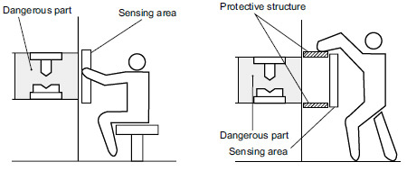
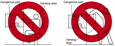
Sensing area
- Make sure to install this device such that any part of the human body must pass through its sensing area in order to reach the dangerous parts of the machinery. If the human body is not detected, there is a danger of serious injury or death.
- Do not use any reflective type or retroreflective type arrangement.
- Multiple receivers (emitters) cannot be connected for use with a single emitter (receiver).
|
|
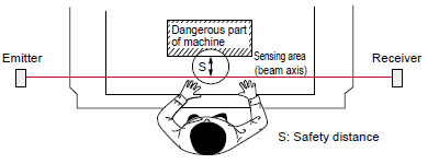
Safety distance
- Calculate the safety distance correctly, and always maintain a distance which is equal to or greater than the safety distance, between the sensing area of this safety light curtain and the dangerous parts of the machinery.
(Please check the latest standards for the equation.) If the safety distance is miscalculated or if sufficient distance is not maintained, there is a danger of serious injury or death. - Before designing the system, refer to the relevant standards of the region where this device is to be used and then install this device.
|
- The sizes of the minimum sensing objects for this device vary depending on whether or not the floating blanking function is being used. Calculate the safety distance with the proper size of the minimum sensing object and appropriate equation.
Size of minimum sensing object when applying floating blanking function
Note: Refer to ORDER GUIDE for the floating blanking function. However, the floating blanking function cannot be used with the SF4B-□-01<V2>, the SF4B-□-03<V2> and the SF-C14EX-01.Model No. Min. sensing object when applying floating blanking function Invalid Setting (Note) 1 beam channel 2 beam channels 3 beam channels SF4B-F□(G) (Min. sensing object ø14 mm ø0.551 in) ø14 mm ø0.551 in ø24 mm ø0.945 in ø34 mm ø1.339 in ø44 mm ø1.732 in SF4B-H□(G) (Min. sensing object ø25 mm ø0.984 in) ø25 mm ø0.984 in ø45 mm ø1.772 in ø65 mm ø2.559 in ø85 mm ø3.346 in SF4B-A□(G) (Min. sensing object ø45 mm ø1.772 in) ø45 mm ø1.772 in ø85 mm ø3.346 in ø125 mm ø4.921 in ø165 mm ø6.496 in
- The safety distance is calculated using the equations given on the following pages when a person moves perpendicularly (normal intrusion) into the sensing area of the device.
If the intrusion direction is not perpendicular, always check the related standards (regional, machine standards, etc.)
| For use based on EN ISO 13855 / ISO 13855 / JIS B 9715 |
For intrusion direction perpendicular to the sensing area
<In case that the minimum sensing object is ø40 mm ø1.575 in or less>
• Equation① S=K×T+C
| S: | Safety distance (mm) Minimum required distance between the sensing area surface and the dangerous parts of the machine |
|---|---|
| K: | Intrusion velocity of operator’s body or object (mm/sec.) Normally taken as 2,000 (mm/sec.) for calculation |
| T: | Response time of total equipment (sec.) T=Tm+TSF4B Tm:Maximum halting time of machinery (sec.) TSF4B:Response time of the SF4B / SF4B-G series (sec.) |
| C: | Additional distance calculated from the size of the minimum sensing object of the safety light curtain (mm) However, the value of “C” cannot be less than 0. C= 8 × (d – 14) d: Minimum sensing object diameter (mm) |
| ・ | For calculating the safety distance “S”, there are the following five cases. First calculate by substituting the value K = 2,000 (mm/sec.) in the equation above. Then, classify the obtained value of “S” into three cases, 1) S < 100, 2) 100 ≤ S ≤ 500, and 3) S > 500. For Case 3) S > 500, recalculate by substituting the value < = 1,600 (mm/ sec.). After that, classify the calculation result into two cases, 4) S ≤ 500 and 5) S > 500. For details, refer to the instruction manual enclosed with this product. For calculating “Tm” (maximum halt time of the machinery), use a special device called a “brake monitor”. When this device is used in the “PSDI mode”, an appropriate safety distance “S” must be calculated. For details, be sure to refer to the standards or regulations applicable in each region or country. |
|---|
<In the case that the minimum sensing object is ø40 mm ø1.575 in or more>
• Equation S=K×T+C
| S: | Safety distance (mm) |
|---|---|
| K: | Intrusion velocity of operator’s body or object (mm/sec.) Taken as 1,600 (mm/sec.) for calculation |
| T: | Response time of total equipment (sec.) T=Tm+TSF4B Tm:Maximum halting time of machinery (sec.) TSF4B:Response time of the SF4B / SF4B-G series (sec.) |
| C: | Additional distance calculated from the size of the minimum sensing object of the safety light curtain (mm) C = 850 (mm) (Constant) |
| For use based on ANSI B11.19 |
• Equation ② S=K×(TS+TC+TSF4B+Tbm)+Dpf
| S: | Safety distance (mm) Minimum required distance between the sensing area surface and the dangerous parts of the machine |
|---|---|
| K: | Intrusion velocity {Recommended value in OSHA is 63 (inch/sec.) ≈ 1,600 (mm/sec.)} ANSI B11.19 does not define the intrusion velocity “K”. When determining “K”, consider possible factors including physical ability of operators. |
| TS: | Halting time calculated from the operation time of the control element (air valve, etc.) (sec.) |
| TC: | Maximum response time of the control circuit required for functioning the brake (sec.) |
| TSF4B: | Response time of safety light curtain (sec.) |
| Tbm: | Additional halting time tolerance for the brake monitor (sec.) The following equation holds when the machine is equipped with a brake monitor. Tbm=Ta-(TS+TC) Ta:Setting time of brake monitor (sec.) When the machine is not equipped with a brake monitor, it is recommended that 20 % or more of (TS+TC) is taken as additional halting time. |
| Dpf: | Additional distance calculated from the size of the minimum sensing of the safety light curtain (mm) SF4B-F□(G)<V2> Dpf=23.8mm 0.937 in SF4B-H□(G□)<V2> Dpf=61.2mm 2.409 in SF4B-A□(G)<V2> Dpf=129.2mm 5.087 in [Dpf=3.4×(d-0.276)(inch)≒3.4×(d-7)(mm) d:Minimum sensing object diameter 0.552(inch)≒14(mm)SF4B-F□(G)<V2> Minimum sensing object diameter 0.985(inch)≒25(mm)SF4B-H□(G□)<V2> Minimum sensing object diameter 1.772(inch)≒455(mm)SF4B-A□(G<V2> ] |
Handy-controller
- This device enables to set each function using the handy-controller SFB-HC (optional). (However, a handy-controller cannot be used with the SF4B-□-01<V2>, the SF4B-□-03<V2> and the SF-C14EX-01.) Among the functions, the contents related to the safety distance such as the size of the minimum sensing object and response time are varied depending on the setting condition. When setting each function, re-calculate the safety distance, and make enough space larger than the calculated safety distance. Failure to do so might cause the accident that the device cannot stop quickly before reaching the dangerous area of the machinery, resulting in the serious injury or death.
| ・ | Refer to the instruction manual of the handy-controller for details of the function settings for using handycontroller SFB-HC (optional). |
|---|
Corner mirror
- Be sure to carry out maintenance while referring to the instruction manual for the SF4B / SF4B-G series of safety light curtains.
- Do not use if dirt, water, or oil, etc. is attached to the reflective surface of this product. Appropriate sensing range may not be maintained due to diffusion or refraction.
- Make sure that you have read the instruction manual for the corner mirror thoroughly before setting up the corner mirrors and safety light curtains, and follow the instructions given. If the equipment is not set up correctly as stipulated in the instruction manual, incident light errors may result in unexpected situations which may result in serious injury or death.
- Please download the instruction manuals from our website.
- Safety light curtain SF4B / SF4B-G series cannot be used as a retroreflective type. Avoid installing the safety light curtain as a retroreflective type when this product is applied.
- The mirror part of this product is made of glass. Note that if it is broken, the glass shards may fly apart.
- Do not use if crack or breakage appears on the reflective surface of this product. Proper sensing range may not be maintained due to diffusion or refraction.
If crack or breakage appears on the reflective surface of this product, replace the product. - When adjusting beam channels with a laser alignment tool, etc., take sufficient care that the laser beam reflected by this product does not enter the eyes.
- Failure to follow the above items may result in death or serious injury.
BY EMAIL
- U.S.A.
- +1-800-344-2112
- Europe
- +49-89-45354-1000
- China
- +86-10-59255988
- Singapore
- +65-6299-9181


Requests to customers (Automation Control Components & Industrial Device) [Excluding specific product]
Requests to customers (Automation Control Components & Industrial Device) [For specific product]
Requests to customers (FA Sensors & Components [Excluding motors])
Requests to customers (Dedicated to industrial motors)
- COMPONENTS & DEVICES
- FA SENSORS & COMPONENTS
- Fiber Sensors
- Photoelectric Sensors / Laser Sensors
- Micro Photoelectric Sensors
- Light Curtains / Safety Components
- Area Sensors
- Inductive Proximity Sensors
- Particular Use Sensors
- Sensor Options
- Wire-Saving Systems
- Programmable Controllers / Interface Terminal
- Human Machine Interface
- Pressure Sensors / Flow Sensors
- Measurement Sensors
- Static Control Devices
- Laser Markers / 2D Code Readers
- Machine Vision System
- Energy Management Solutions
- Timers / Counters / FA Components
- MOTORS
![]()