[System Maintenance Notice]
Due to ongoing system maintenance, the site search and specification search functions are temporarily unavailable. We apologize for any inconvenience this may cause and appreciate your understanding.
【Notification of Manufacturer Change for Panasonic Industrial Devices SUNX Products and Panasonic Industrial Devices SUNX Tatsuno Products】
From April 1, 2024, the terms "Panasonic Industrial Devices SUNX Co., Ltd." and "Panasonic Industrial Devices SUNX Tatsuno Co., Ltd."
in this page and in the manuals and other documents to be downloaded will all be replaced with "Panasonic Industry Co., Ltd." and applied accordingly.

 Business
> Industrial Devices
> Automation Controls Top
> FA Sensors & Components
> Sensors
> Light Curtains / Safety Components
> Safety Light Curtain Type 4 SF4B Ver.2(Discontinued Products)
> I/O Circuit and Wiring diagrams
Business
> Industrial Devices
> Automation Controls Top
> FA Sensors & Components
> Sensors
> Light Curtains / Safety Components
> Safety Light Curtain Type 4 SF4B Ver.2(Discontinued Products)
> I/O Circuit and Wiring diagrams
Safety Light Curtain Type 4 SF4B Ver.2 (Discontinued Products)
|
We are sorry, the products have been discontinued. Please refer to the details of the discontinued products and the recommended substitutes list below.
|
I/O Circuit and Wiring diagrams
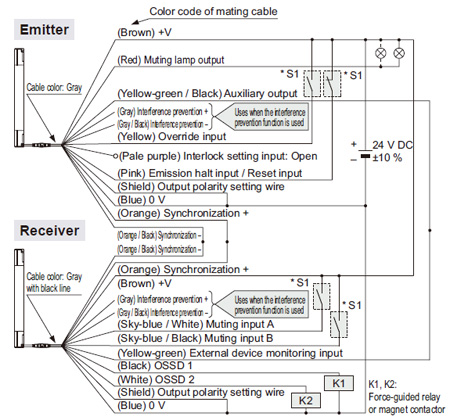
I/O circuit diagram
<In case of using I/O circuit for PNP output>
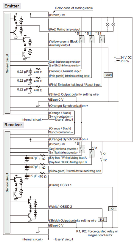
| Note: | The above diagram is when using a 12-core cable. If an 8-core cable is used, the red, yellow, gray, gray / black, sky-blue / white and sky-blue / black lead wires are absent. |
|---|
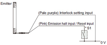
*S1
| Switch S1 | |
| ・ | Emission halt input / Reset input For manual reset Vs to Vs – 2.5 V (sink current 5 mA or less): Emission halt (Note 1) Open: Emission For automatic reset Vs to Vs – 2.5 V (sink current 5 mA or less): Emission (Note 1) Open: Emission halt |
|---|---|
| ・ | Interlock setting input, Override input, Muting input A / B, External device monitoring input Vs to Vs – 2.5 V (sink current 5 mA or less): Enabled (Note 1) Open: Disabled |
| Note: | Vs is the applying supply voltage. |
|---|
<In case of using I/O circuit for NPN output>
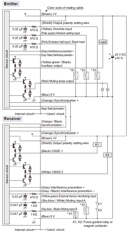
| Note: | The above diagram is when using a 12-core cable. If an 8-core cable is used, the red, yellow, gray, gray / black, sky-blue / white and sky-blue / black lead wires are absent. |
|---|
*S1
| Switch S1 | |
| ・ | Emission halt input / Reset input For manual reset 0 to +1.5 V (source current 5 mA or less): Emission halt Open: Emission For automatic reset 0 to +1.5 V (source current 5 mA or less): Emission Open: Emission halt |
|---|---|
| ・ | Interlock setting input, Override input, Muting input A / B, External device monitor input 0 to +1.5 V (source current 5 mA or less): Enabled Open: Disabled |
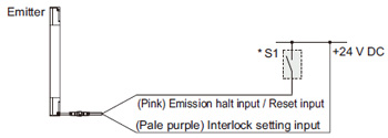
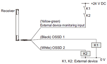
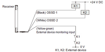
Connection example
| Standard components (8-core cable): Interlock function “enabled (manual reset)”, external device monitoring function “enabled” |
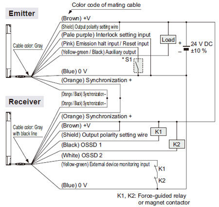
<In case of using I/O circuit for PNP output>
*S1
| Switch S1 | |
| ・ | Emission halt input / Reset input For manual reset Vs to Vs – 2.5 V (sink current 5 mA or less): Emission halt (Note) Open: Emission For automatic reset Vs to Vs – 2.5 V (sink current 5 mA or less): Emission (Note) Open: Emission halt |
|---|---|
| Note: | Vs is the applying supply voltage. |
|---|
The diagram at above shows the configuration when using PNP output, interlock function “enabled (manual reset)” and external device monitoring function “enabled”.
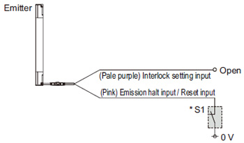
| In case of setting the interlock function to “disabled (automatic reset)” |
*Refer to the SF4B<V2> instruction manual for details of the interlock function.
| In case of setting the external device monitoring function to “disabled” |
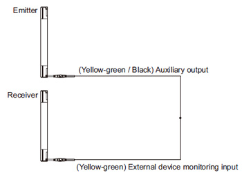
*Refer to the SF4B<V2> instruction manual for details of the external device monitoring function.
<In case of using I/O circuit for NPN output>
*S1
| Switch S1 | |
| ・ | Emission halt input / Reset input For manual reset 0 to +1.5 V (source current 5 mA or less): Emission halt Open: Emission For automatic reset 0 to +1.5 V (source current 5 mA or less): Emission Open: Emission halt |
|---|---|
The diagram at above shows the configuration when using NPN output, interlock function “enabled (manual reset)” and external device monitoring function “enabled”.
| In case of setting the interlock function to “disabled (automatic reset)” |
*Refer to the SF4B<V2> instruction manual for details of the interlock function.
| In case of setting the external device monitoring function to “disabled” |
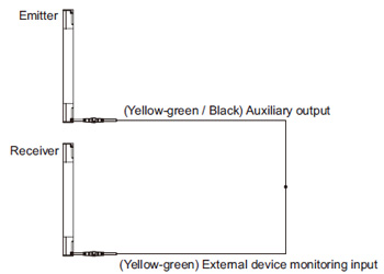
*Refer to the SF4B<V2>instruction manual for details of the external device monitoring function.
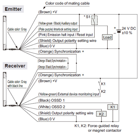
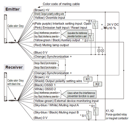
Connection example
| Muting control components (12-core cable, with interference prevention wires): Interlock function “disabled (automatic reset)”, external device monitoring function “disabled” |
<In case of using I/O circuit for PNP output>
*S1
| Switch S1 | |
| ・ | Emission halt input / Reset input For manual reset Vs to Vs – 2.5 V (sink current 5 mA or less): Emission halt (Note), Open: Emission For automatic reset Vs to Vs – 2.5 V (sink current 5 mA or less): Emission (Note), Open: Emission halt |
|---|---|
| ・ | Override input, Muting input A / B, External device monitoring input Vs to Vs – 2.5 V (sink current 5 mA or less): Enabled (Note), Open: Disabled |
| Note: | Vs is the applying supply voltage. |
|---|
The diagram at above shows the configuration when using PNP output, interlock function “disabled (automatic reset)” and external device monitoring function “disabled”.
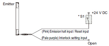
| In case of setting the interlock function to “enabled (manual reset)” |
- When the interlock function is “enabled (manual reset)”, the override function cannot be used.
*Refer to the SF4B<V2> instruction manual for details of the interlock function.
| In case of setting the external device monitoring function to “enabled” |
*Refer to the SF4B<V2> instruction manual for details of the external device monitoring function.
<In case of using I/O circuit for NPN output>
*S1
| Switch S1 | |
| ・ | Emission halt input / Reset input For manual reset 0 to +1.5 V (source current 5 mA or less): Emission halt, Open: Emission For automatic reset 0 to +1.5 V (source current 5 mA or less): Emission, Open: Emission halt |
|---|---|
| ・ | Override input, Muting input A / B, External device monitoring input 0 to +1.5 V (source current 5 mA or less): Enabled, Open: Disabled |
The diagram at above shows the configuration when using NPN output, interlock function “disabled (automatic reset)” and external device monitoring function “disabled”.
| In case of setting the interlock function to “enabled (manual reset)” |
- When the interlock function is “enabled (manual reset)”, the override function cannot be used.
*Refer to the SF4B<V2> instruction manual for details of the interlock function.
| In case of setting the external device monitoring function to “enabled” |
*Refer to the SF4B<V2> instruction manual for details of the external device monitoring function.
SF-C11
SF4B / SF4B-G series wiring diagram (Control Category 4)
| For PNP output (minus ground) |
- Set the safety light curtain input polarity selection switch to the PNP side and ground the 0 V line.
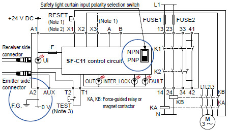
Notes:
| 1) | The above diagram is when using manual reset. If automatic reset is used, disconnect the lead from X2 and connect it to X3. In this case, a reset (RESET) button is not needed. |
|---|---|
| 2) | Use a momentary-type switch as the reset (RESET) button. |
| 3) | Emission halt occurs when the test (TEST) button is open, and emission occurs when the test (TEST) button is short-circuited. If not using the test (TEST) button, short-circuit T1 and T2. |
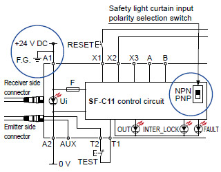
| For NPN output (plus ground) |
|
|
| When SF-C11 is connected to the safety light curtain, be sure to use the following mating cable. SFB-CB□, SFB-CCJ10□ |
Terminal arrangement diagram
|
|
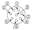
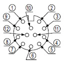
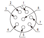
Pin layout for safety light curtain connectors
|
|
SF-C12
SF4B / SF4B-G series wiring diagram (Control Category 4)
| For PNP output (minus ground) |
- Set the two safety light curtain input polarity select switches to the PNP side and connect the FG terminal to the 0 V line.
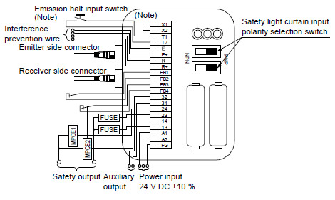
| Note: | The above diagram is when using manual reset. If automatic reset is used, connect a normally closed type pushbutton switch between T1 and T2 and leave between X1 and X2 open. |
|---|
| For NPN output (plus ground) |
- In the above diagram, set the two safety light curtain input polarity selection switches to the NPN side and connect the F.G. terminal to the + side.
| When SF-C12 is connected to the safety light curtain, be sure to use the following mating cable. SFB-CB05-MU, SFB-CCJ10□-MU |
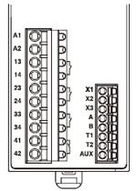
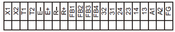
Terminal arrangement diagram |
 |
|
|
Pin layout for safety light curtain connectors
|
|
SF-C13
SF4B / SF4B-G series wiring diagram (Control Category 4)
- Connect the safety light curtain control outputs OSSD 1 and OSSD 2 to S1 and S2 respectively.
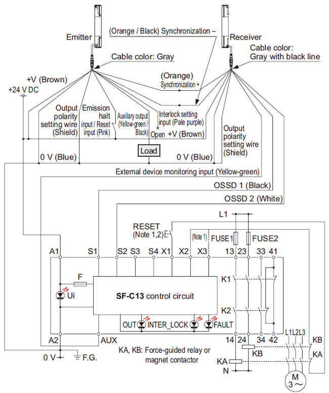
Notes:
| 1) | The above diagram is when using manual reset. If automatic reset is used, disconnect the lead from X2 and connect it to X3. In this case, a reset (RESET) button is not needed. |
|---|---|
| 2) | Use a momentary-type switch as the reset (RESET) button. |
| For NPN output (plus ground) |
- Connect the safety light curtain control outputs OSSD 1 and OSSD 2 to S4 and S2 respectively and ground the + side.
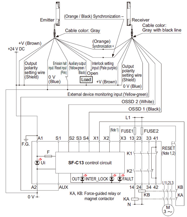
Notes:
| 1) | The above diagram is when using manual reset. If automatic reset is used, disconnect the lead from X2 and connect it to X3. In this case, a reset (RESET) button is not needed. |
|---|---|
| 2) | Use a momentary-type switch as the reset (RESET) button. |
| When SF-C13 is connected to the safety light curtain, be sure to use the following descrete wire mating cable. SFB-CCB□(-MU), SFB-CC□(-MU) |
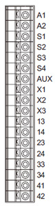
Terminal arrangement diagram
|
|
SF-C14EX(-01)
SF4B / SF4B-G series wiring diagram (Control Category 4)
| For PNP output (minus ground) |
- Set the output polarity selection switch to the PNP side and ground the 0 V line.
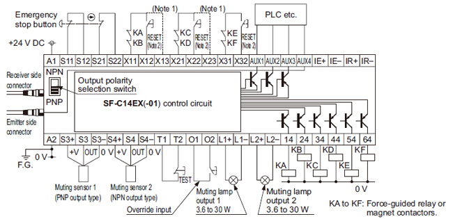
Notes:
| 1) | The above diagram is when using manual reset.If automatic reset is used, disconnect the lead from X12 and connect it to X13,and disconnect the lead from X22 and connect it to X23, as shown by the dotted lines. In this case, a reset (RESET) button is not needed. Terminals X31 to X32 are for manual reset only. |
|---|---|
| 2) | Use a momentary-type switch for the reset (RESET) button. |
| For NPN output (plus ground) |
- Set the output polarity selection switch to the NPN side and ground the side of the power supply input.
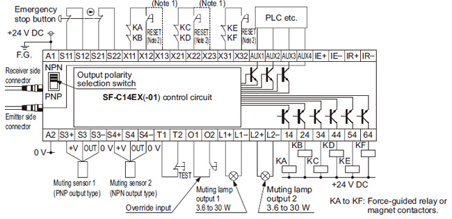
Notes:
| 1) | The left diagram is when using manual reset. If automatic reset is used, disconnect the lead from X12 and connect it to X13, and disconnect the lead from X22 and connect it to X23, as shown by the dotted lines. In this case, a reset (RESET) button is not needed. Terminals X31 to X32 are for manual reset only. |
|---|---|
| 2) | Use a momentary-type switch for the reset (RESET) button. |
| ・ | When SF-C14EX is connected to the safety safety light curtain, be sure to use the following mating cable. SFB-CB□-EX, SFB-CCJ10□ |
|---|---|
| ・ | If the NO (Normally Open) contact switch is used as a muting sensor, f wire it as shown in the figure below. 
|
| ・ | If the emergency stop button is not used, short-circuit between the terminals S11 to S12 and S21 to S22 directly. |
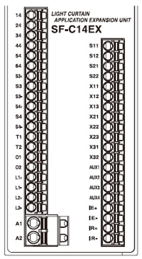
Terminal arrangement diagram
|
|
||||||||||||||||||||||||||||||||||||||||||||||||||||||||||||||||||||||||||
| Pin layout for safety light curtain connectors |
|
|
BY EMAIL
- U.S.A.
- +1-800-344-2112
- Europe
- +49-89-45354-1000
- China
- +86-10-59255988
- Singapore
- +65-6299-9181


Requests to customers (Automation Control Components & Industrial Device) [Excluding specific product]
Requests to customers (Automation Control Components & Industrial Device) [For specific product]
Requests to customers (FA Sensors & Components [Excluding motors])
Requests to customers (Dedicated to industrial motors)
- COMPONENTS & DEVICES
- FA SENSORS & COMPONENTS
- Fiber Sensors
- Photoelectric Sensors / Laser Sensors
- Micro Photoelectric Sensors
- Light Curtains / Safety Components
- Area Sensors
- Inductive Proximity Sensors
- Particular Use Sensors
- Sensor Options
- Wire-Saving Systems
- Programmable Controllers / Interface Terminal
- Human Machine Interface
- Pressure Sensors / Flow Sensors
- Measurement Sensors
- Static Control Devices
- Laser Markers / 2D Code Readers
- Machine Vision System
- Energy Management Solutions
- Timers / Counters / FA Components
- MOTORS
![]()