[System Maintenance Notice]
Due to ongoing system maintenance, the site search and specification search functions are temporarily unavailable. We apologize for any inconvenience this may cause and appreciate your understanding.
【Notification of Manufacturer Change for Panasonic Industrial Devices SUNX Products and Panasonic Industrial Devices SUNX Tatsuno Products】
From April 1, 2024, the terms "Panasonic Industrial Devices SUNX Co., Ltd." and "Panasonic Industrial Devices SUNX Tatsuno Co., Ltd."
in this page and in the manuals and other documents to be downloaded will all be replaced with "Panasonic Industry Co., Ltd." and applied accordingly.

 Business
> Industrial Devices
> Automation Controls Top
> FA Sensors & Components
> Sensors
> Light Curtains / Safety Components
> Non-Contact Safety Door Switch SG-P
> Cautions For Use
Business
> Industrial Devices
> Automation Controls Top
> FA Sensors & Components
> Sensors
> Light Curtains / Safety Components
> Non-Contact Safety Door Switch SG-P
> Cautions For Use
Non-Contact Safety Door Switch SG-P
|
Cautions For Use
| ・ | This Web site is a guide to select a suitable product. Be sure to read instruction manual attached to the product prior to its use. |
|---|
- The customer is responsible for ensuring the safety of the entire system and the compliance with the standards applicable in the country / region of use.
Machine designer, installer, employer and operator
- The machine designer, installer, employer and operator are solely responsible to ensure that all applicable legal requirements relating to the installation and the use in any application are satisfied and all instructions for installation and maintenance contained in the instruction manual are followed.
- Whether this device functions as intended to and systems including this device comply with safety regulations depends on the appropriateness of the application, installation, maintenance and operation. The machine designer, installer, employer and operator are solely responsible for these items.
- This product has been developed / produced for industrial use only.
- This product is an extremely low power radio device and complies with the Japanese Radio Act. There is no need to obtain a radio station license to use the product in Japan.
- Do not use this product near equipment that emits strong electromagnetic waves.
- If the power supply used for this device is shared by other devices, the device may be affected by noise emitted from other devices. Do not share the power supply used for this device with other devices.
- The switch body of this product must be connected to a power supply unit and a safety device such as a safety controller. Power supply unit and safety controller must be purchased separately.
- The power supply unit used for this device must satisfy the following requirements.
- The power supply unit must be certified for use in your region.
- The power supply unit must have the rated output voltage of 24 V DC +10 -20 % and the ripple (P-P) of 10 % or less.
- The power supply with SELV (Secondary Extra Low Voltage) or PELV (Protective Extra Low Voltage) that comply with the RE Directive must be used. (When CE Marking is required)
- The power supply must comply with Class 2 defined by UL508 or satisfy the output characteristics requirements of the limited voltage and current circuit.
- The power supply unit must have reinforced insulation or double insulation between the primary circuit and secondary circuit.
- When using a commercial switching regulator, the frame ground (F.G.) terminal must be connected to ground.
- The power supply unit must have an output holding time of 20 ms or more.
- If surges occur, take countermeasures such as connecting a surge absorber to the source of the surges.
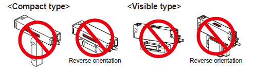
Mounting
- Do not install the switch body of this device on a movable door.
- Mount the switch body carefully so that it does not come in contact with the movable door.
- Mount the switch body in a location where it cannot be reached or it is hidden so that it cannot be easily disabled. Or, mount the switch body in such a way that it cannot be removed with ordinary tools.
|
|
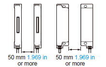
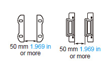
Mutual Interference
When multiple devices are installed next to one another, mutual interference may occur and cause malfunctioning. When using them next to one another, provide a distance between one another as shown below.
|
|
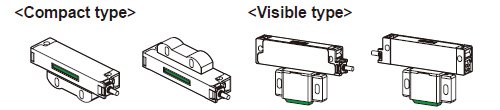
Part description
|
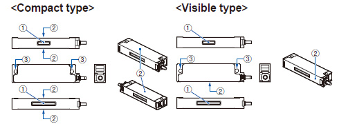
| No. | Name | Function | |
|---|---|---|---|
| ① | Indicator | Lights green |
When the actuator is detected |
Lights red |
When the actuator is not detected | ||
Blinks red |
• Lockout state, error occurrence • When the teaching sequence was incorrect (only when using highcode models SG-P20□-□) |
||
Blinks green |
When other switch bodies (standard unit, sub unit) in series connection do not detect actuators, when error occurs | ||
Lights yellow (Simultaneously light green and red) (Note) |
After the power supply is turned ON, during self-diagnosis | ||
| Alternately blinking red to yellow 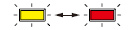 (lights red, blinking green) (Note) |
When an unpaired actuator is detected (only when using highcode models SG-P20□-□) | ||
| ② | Actuator detection surface | When the actuator is brought near to the surface, the switch body detects the actuator. | |
| ③ | Mounting hole | Use M4 screws (length: 20 mm 0.787 in or more), flat washers and spring washers (not supplied with the product) to install the switch body to the equipment body or guard. The screws should be tightened with a torque of 1.2 N∙m. | |
| Note : | When you look at a lit LED on a visible type model through the actuator, the LED may sometimes appear green in some part and red in other part. |
|---|
Actuator
|
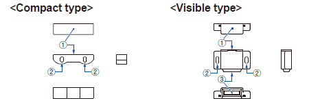
| No. | Name | Function | ① | Switch body detection surface | When the actuator is brought near to the switch body, the switch body detects the actuator. |
|---|---|---|
| ② | Mounting hole | Use M4 screws (length: 20 mm 0.787 in or more), flat washers and spring washers (not supplied with the product) to install the actuator to the door. The screws should be tightened with a torque of 1.2 N∙m. |
| ③ | Transmission part | The light of the indicator is transmitted through the part. |
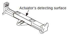
| About maintenance actuators (optional) |
- Using a maintenance actuator incorrectly can lead to an accident. Be sure to understand the operation of the system when using a maintenance actuator to use maintenance actuators correctly.
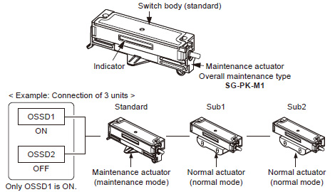
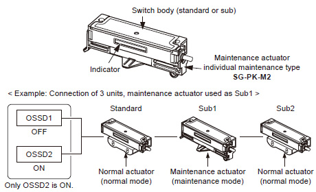
By directly mounting the maintenance actuator to the switch body while the door is open, it is possible to distinguish accidental opening of the door. Two types of maintenance actuators are available: overall maintenance type (SG-PK-M1) and individual maintenance type (SG-PK-M2 (Note)).
Note: In the case of the individual maintenance type SG-PK-M2, multiple units can be installed and used simultaneously.
|
| Type | Overall maintenance type | Individual maintenance type |
|---|---|---|
| Model No. | SG-PK-M1 | SG-PK-M2 |
| Ambient temperature | 0 to +40 ℃ 0 to +104 ℉ (No dew condensation), Storage: -25 to +65 ℃ -13 to +149 ℉ |
|
| Ambient humidity | 35 to 85 % RH, storage: 35 to 85 % RH | |
| Vibration resistance | 10 to 55Hz, 1 mm double amplitude, 2 hours each in X, Y, and Z directions | |
| Shock resistance | 300 m/s2 (30 G approx.), 3 times each in X, Y, and Z direction |
|
| Material | POM (polyacetal) | |
| Weight | 7 g approx. | |
| ・ | Overall maintenance type (SG-PK-M1) can be used only on standard switch bodies. |
|---|---|
| ・ | Individual maintenance type (SG-PK-M2) can be used on standard and sub switch bodies. |
| ・ | When maintenance actuators are used, redundant input monitoring (dual channel monitoring) of OSSD1and OSSD2 for the SG-P series by a safety controller, etc. cannot be used. |
| ・ | When using a maintenance actuator, be careful that the normal actuator will not be detected at the same time. |
| ・ | Determine whether to use the normal mode or maintenance mode according to the system. |
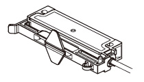
Installation
|
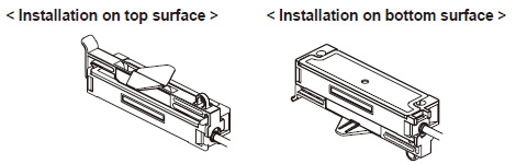
|
Output operation and indicator operation
Operation differs between the overall maintenance type (SG‑PK‑M1) and individual maintenance type (SG‑PK‑M2). The output operation and indicator operation of the switch body when used with each maintenance actuator is as follows
|
| Type | Standard | Sub1 | Sub2 | OSSD1 | OSSD2 | |||||||
|---|---|---|---|---|---|---|---|---|---|---|---|---|
| Actuator | Detection Status | Indicator | Actuator | Detection Status | Indicator | Actuator | Detection Status | Indicator | ||||
| Overall Mainte- nance |
Mainte- nance |
Detection | Yellow | Normal | Detection | Yellow | Normal | Detection | Yellow | ON | OFF | |
| Detection | Yellow | Detection | Yellow | Not detected | Red | ON | OFF | |||||
| Detection | Yellow | Not detected | Red | Detection | Yellow | ON | OFF | |||||
| Not detected | Red | Detection | Blinks green |
Detection | Blinks green |
OFF | OFF | |||||
| After 12 hours (Note 1) |
Detection | Blinks yellow/ red |
Detection | Blinks yellow/ red |
Detection | Blinks yellow/ red |
OFF | OFF | ||||
Notes:
| 1) | Maintenance actuator can operate continuously for up to 12 hours. After 12 hours, OSSD1 turns OFF automatically and the indicator on the switch body blinks in yellow / red. To use the maintenance actuator again, detach the actuator and reinstall. |
|---|---|
| 2) | The indicator on the switch body blinks in yellow or red to indicate one of the two modes. For details, see the Instruction Manual of the SG-P series. |
|
| Type | Standard | Sub1 | Sub2 | OSSD1 | OSSD2 | |||||||
|---|---|---|---|---|---|---|---|---|---|---|---|---|
| Actuator | Detection Status | Indicator | Actuator | Detection Status | Indicator | Actuator | Detection Status | Indicator | ||||
| Indi- vidual Mainte- nance |
Normal | Detection | Yellow | Mainte- nance |
Detection | Yellow | Normal | Detection | Yellow | OFF | ON | |
| Not detected |
Red | Detection | Blinks yellow/ red |
Detection | Blinks yellow/ red |
OFF | OFF | |||||
| Detection | Blinks green |
Not detected |
Red | Detection | Blinks green |
OFF | OFF | |||||
| After 12 hours (Note) |
Detection | Blinks yellow/ red |
Detection | Blinks yellow/ red |
Detection | Blinks yellow/ red |
OFF | OFF | ||||
| Note : | Maintenance actuator can operate continuously for up to 12 hours. After 12 hours, OSSD2 turns OFF automatically and the indicator on the switch body blinks in yellow / red. To use the maintenance actuator again, detach the actuator and reinstall. |
|---|
BY EMAIL
- U.S.A.
- +1-800-344-2112
- Europe
- +49-89-45354-1000
- China
- +86-10-59255988
- Singapore
- +65-6299-9181


Requests to customers (Automation Control Components & Industrial Device) [Excluding specific product]
Requests to customers (Automation Control Components & Industrial Device) [For specific product]
Requests to customers (FA Sensors & Components [Excluding motors])
Requests to customers (Dedicated to industrial motors)
- COMPONENTS & DEVICES
- FA SENSORS & COMPONENTS
- Fiber Sensors
- Photoelectric Sensors / Laser Sensors
- Micro Photoelectric Sensors
- Light Curtains / Safety Components
- Area Sensors
- Inductive Proximity Sensors
- Particular Use Sensors
- Sensor Options
- Wire-Saving Systems
- Programmable Controllers / Interface Terminal
- Human Machine Interface
- Pressure Sensors / Flow Sensors
- Measurement Sensors
- Static Control Devices
- Laser Markers / 2D Code Readers
- Machine Vision System
- Energy Management Solutions
- Timers / Counters / FA Components
- MOTORS
![]()