[System Maintenance Notice]
Due to ongoing system maintenance, the site search and specification search functions are temporarily unavailable. We apologize for any inconvenience this may cause and appreciate your understanding.
【Notification of Manufacturer Change for Panasonic Industrial Devices SUNX Products and Panasonic Industrial Devices SUNX Tatsuno Products】
From April 1, 2024, the terms "Panasonic Industrial Devices SUNX Co., Ltd." and "Panasonic Industrial Devices SUNX Tatsuno Co., Ltd."
in this page and in the manuals and other documents to be downloaded will all be replaced with "Panasonic Industry Co., Ltd." and applied accordingly.
Thin-type Ionizer ER-VW
I/O Circuit and Wiring diagrams
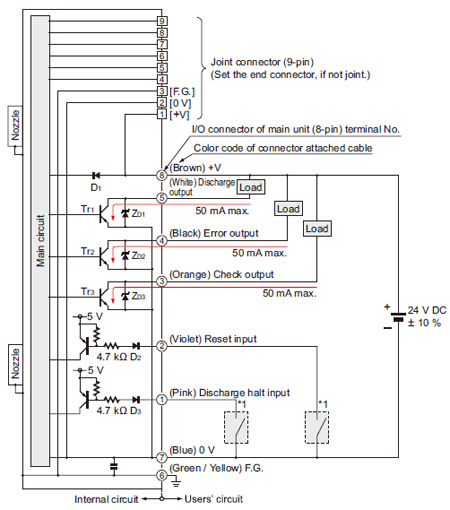
I/O circuit diagram
*1 |
 |
|
| Symbols・・・ |
D1 : Reverse supply polarity protection diode
D2, D3 : Input protection diode
ZD1, ZD2, ZD3 : Surge absorption zener diode
Tr1, Tr2, Tr3 : NPN output transistor |
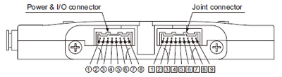
Connector terminal arrangement
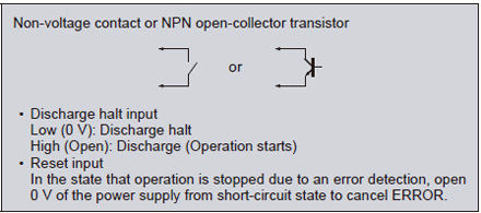
Input signal condition
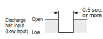
| ・Discharge halt input |
|---|
 |
|
|
| ・Reset input |
|---|
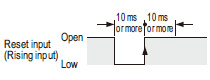 |
|
|
Note:
Repeated control using “Discharge halt input” input should be carried out at 1 Hz or less.
Continuous discharging for 2 sec. or more is required for stable sensing of check output.
If using with repeated control operations that include discharges of 2 sec. or less, use continuous discharges of 2 sec. or more to check the check output when carrying out maintenance.
Return to top
Return to top

 Business
> Industrial Devices
> Automation Controls Top
> FA Sensors & Components
> Static Control Devices
> Static Control Devices
> Thin-type Ionizer ER-VW
> I/O Circuit and Wiring diagrams
Business
> Industrial Devices
> Automation Controls Top
> FA Sensors & Components
> Static Control Devices
> Static Control Devices
> Thin-type Ionizer ER-VW
> I/O Circuit and Wiring diagrams