[System Maintenance Notice]
Due to ongoing system maintenance, the site search and specification search functions are temporarily unavailable. We apologize for any inconvenience this may cause and appreciate your understanding.

 Business
> Industrial Devices
> Automation Controls Top
> FA Sensors & Components
> Motors for FA & Industrial Application
> AC Servo
>
> System Configuration
Business
> Industrial Devices
> Automation Controls Top
> FA Sensors & Components
> Motors for FA & Industrial Application
> AC Servo
>
> System Configuration
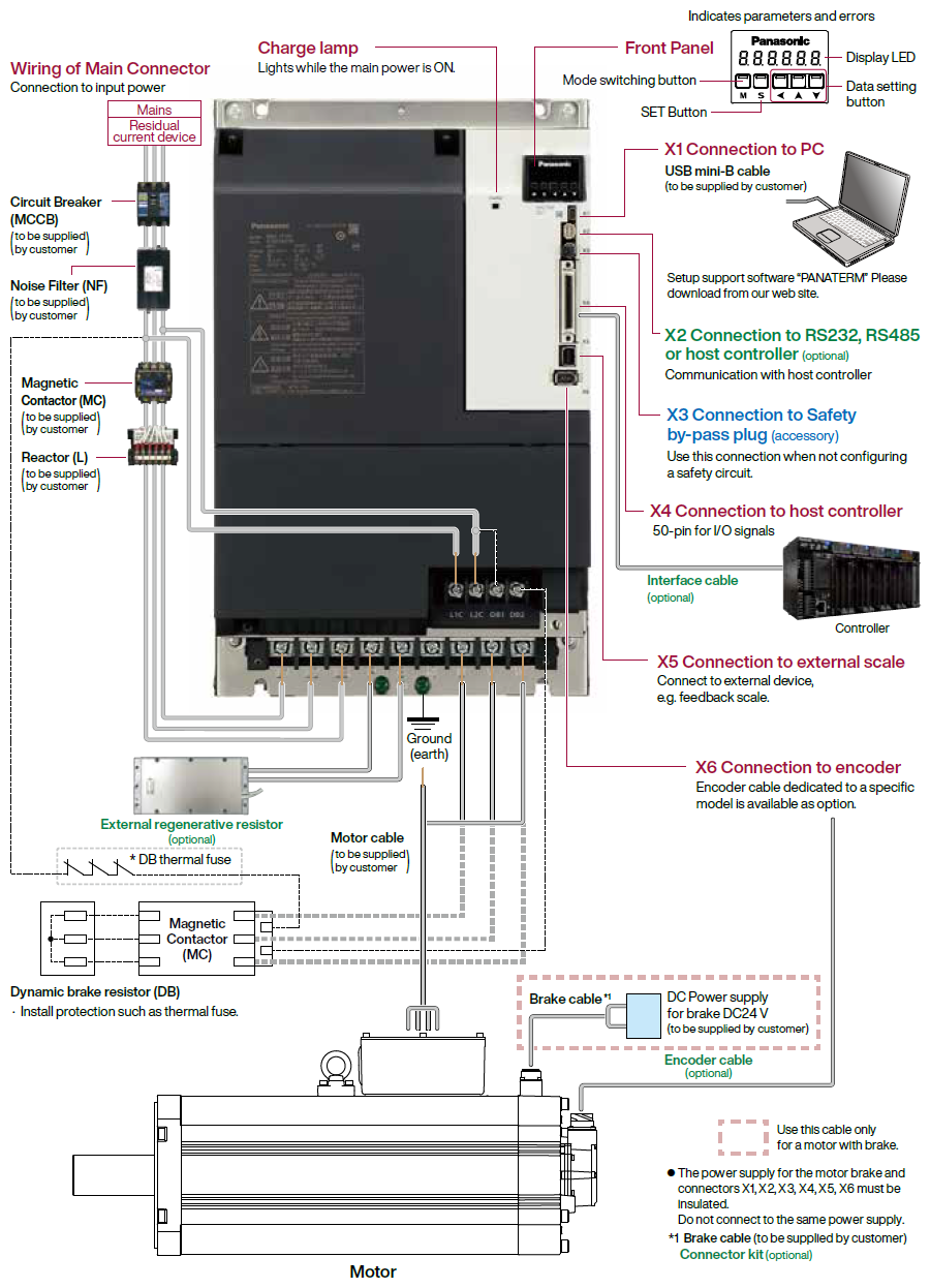
System Configuration
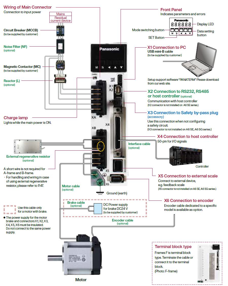
Overall Wiring
A6 SF Series (Driver: A-frame Motor: 200 W)
|
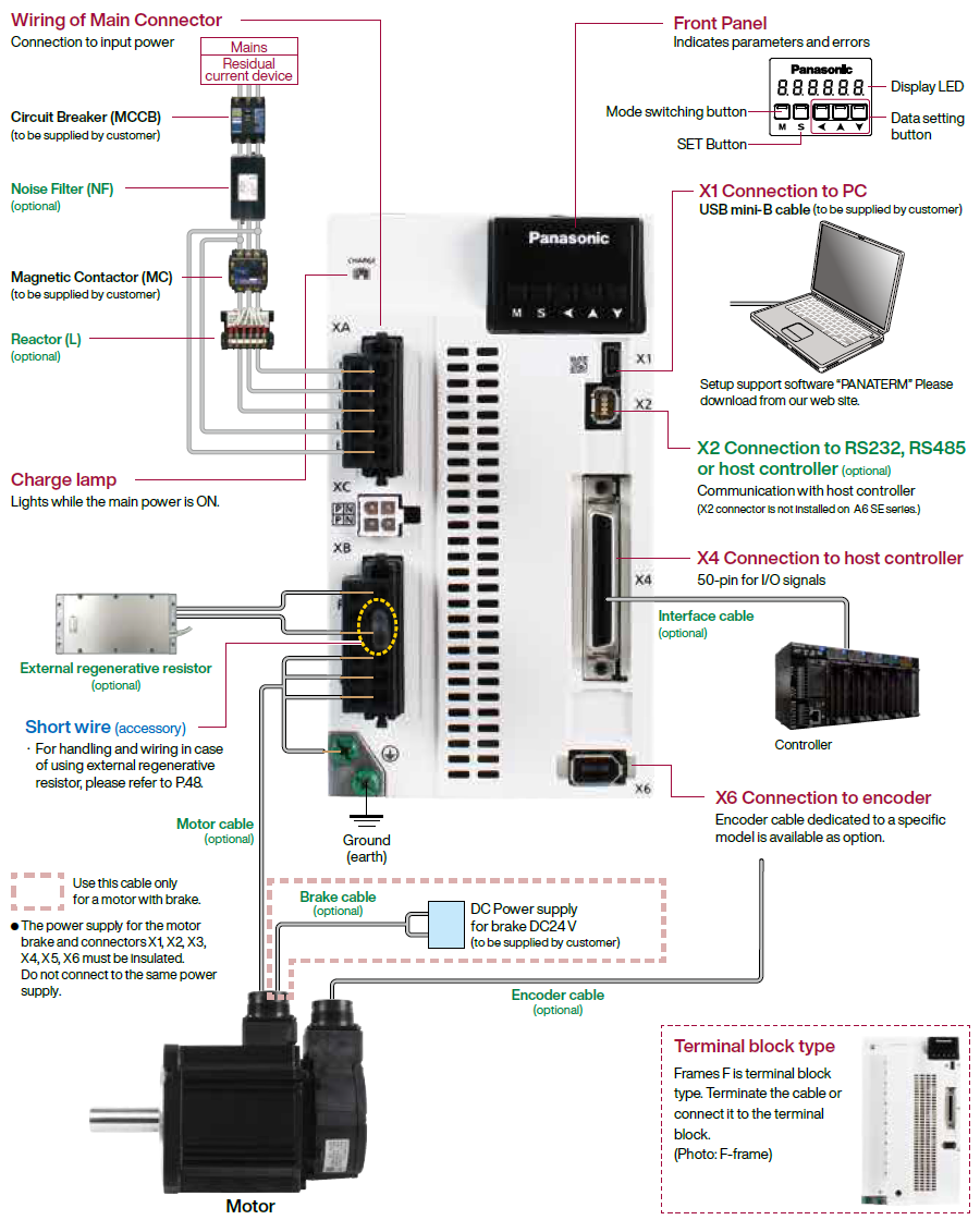
A6 SG Series/ A6 SE Series (Driver: D-frame Motor: 1.0 kW)
|
A6SF Series (Driver: G-frame Motor: 7.5 kW)
|
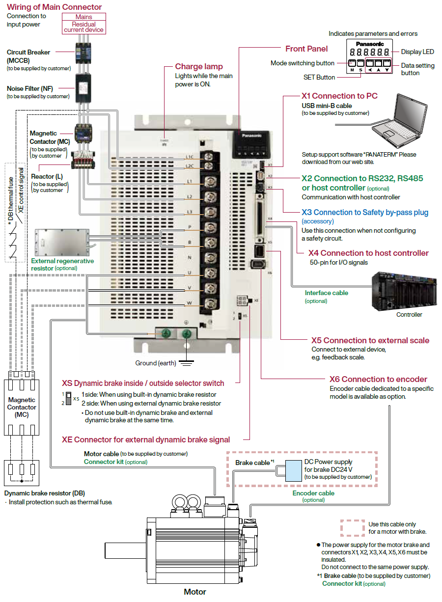
A6SF Series (Driver: H-frame Motor: 22.0 kW)
|
Driver and List of Applicable peripheral devices
| Driver | Applicable motor |
Voltage (V) *1 |
Rated output (kW) |
Required Power ( at the rated load) (kVA) |
Circuit breaker rated (rated current) (A) |
Noise filter (Single phase/ 3-phase ) |
Surge absorber (Single phase/ 3-phase ) |
Ferite core | Rated operating current of magnetic (contactor contact configuration ) *2 |
Diameter and withstand voltage of main circuit cable |
Crimp terminal for main circuit terminal block *3 |
Diameter and withstand voltage of control power supply cable |
Crimp terminal for control power supply terminal block |
Diameter and withstand voltage of motor cable *4 |
Diameter and withstand voltage of brake cable |
|---|---|---|---|---|---|---|---|---|---|---|---|---|---|---|---|
| MADL | MSMF MHMF |
Single phase, 100 |
0.05 | approx. 0.4 |
10 | DV0P4170 | DV0P4190 | DV0P1460 | 20 A (3P+1a) |
0.75 mm2/ AWG18 600 VAC or more to 2.0 mm2/ AWG14 600 VAC or more |
Connection to exclusive connector | 0.75 mm2/ AWG18 600 VAC or more |
Connection to exclusive connector | 0.75 mm2/ AWG18 600 VAC or more to 2.0 mm2/ AWG14 600 VAC or more |
0.28 mm2 to 0.75 mm2/ AWG22 to AWG18 100 VAC or more |
| MSMF MQMF MHMF |
0.1 | ||||||||||||||
| MSMF MHMF |
Single/ 3-phase 200 |
0.05 | approx. 0.5 |
DV0P4170/ DV0PM20042 |
DV0P4190/ DV0P1450 |
||||||||||
| MSMF MQMF MHMF |
0.1, 0.2 | ||||||||||||||
| MBDL | MSMF MQMF MHMF |
Single phase, 100 |
0.2 | DV0P4170 | DV0P4190 | ||||||||||
| Single/ 3-phase 200 |
0.4 | approx. 0.9 |
DV0P4170/ DV0PM20042 |
DV0P4190/ DV0P1450 |
|||||||||||
| MCDL | MSMF MQMF MHMF |
Single phase, 100 |
0.4 | approx. 0.9 |
15 | DV0PM20042 | DV0P4190 | ||||||||
| MSMF MHMF |
Single/ 3-phase 200 |
0.75 | approx. 1.8 |
DV0P4190/ DV0P1450 |
|||||||||||
| MDDL | MGMF | Single/ 3-phase 200 |
0.85 | approx. 2.0 |
20 | DV0P4220 | DV0P4190/ DV0P1450 |
30 A (3P+1a) |
0.75 mm2/ AWG18 100 VAC or more |
||||||
| MSMF | 1.0 (80 mm sq.) |
approx. 2.4 |
|||||||||||||
| MDMF MHMF |
1.0 | ||||||||||||||
| MHMF | 1.0 (80 mm sq.) |
||||||||||||||
| MSMF | 1.0 | ||||||||||||||
| MGMF | 1.3 | approx. 2.6 |
|||||||||||||
| MSMF MDMF MHMF |
1.5 | approx. 2.9 |
|||||||||||||
| MEDL | MGMF | 3-phase 200 |
1.8 | approx. 3.4 |
30 | DV0PM20043 | DV0P1450 | DV0P1460 |
60 A (3P+1a) |
2.0 mm2/ AWG14 600 VAC or more to 3.5 mm2/ AWG12 600 VAC or more |
2.0 mm2/ AWG14 600 VAC or more to 3.5 mm2/ AWG12 600 VAC or more |
||||
| MSMF MDMF MHMF |
2.0 | approx. 3.8 |
|||||||||||||
| MGMF | 2.4 | approx. 4.5 |
3.5 mm2/ AWG12 600 VAC or more |
||||||||||||
| MFDL | MGMF | 3-phase 200 |
2.9 | approx. 5.0 |
50 | DV0P3410 | DV0P1450 | 3.5 mm2/ AWG12 600 VAC or more |
 Terminal block M5 |
|||||
| MSMF MDMF MHMF |
3.0 | approx. 5.2 |
|||||||||||||
| MSMF MDMF MHMF |
4.0 | approx. 6.5 |
100 A (3P+1a) |
||||||||||||
| MGMF | 4.4 | approx. 7.0 |
|||||||||||||
| MSMF MDMF MHMF |
5.0 | approx. 7.8 |
|||||||||||||
| MGDL | MGMF | 3-phase 200 |
5.5 | approx. 8.5 |
60 | HF3080C-SZA (Recommended components ) |
DV0P1450 | DV0P1460 RJ8095 (Recommended components ) T400-61D *5 |
100 A (3P+1a) |
8.0 mm2/ AWG8 600 VAC or more |
 Terminal block M3 |
14 mm2/ AWG6 600 VAC or more |
0.75 mm2/ AWG18 100 VAC or more |
||
| MDMF | 7.5 | approx. 11 |
|||||||||||||
| MHMF | |||||||||||||||
| MHDL | MDMF | 3-phase 200 |
11.0 | approx. 15 |
125 | HF3100C-SZA (Recommended components ) |
DV0P1450 | 150 A (3P+1a) |
22 mm2/ AWG4 600 VAC or more |
 Terminal block M6 |
 Terminal block M4 |
22 mm2/ AWG4 600 VAC or more *6  Terminal block M8 |
|||
| 15.0 | approx. 20 |
||||||||||||||
| 22.0 | approx. 28 |
175 | 38 mm2/ AWG2 600 VAC or more |
*1 Select peripheral devices for single/3phase common specification according to the power source.
*2 The magnetic contactor used for the external dynamic brake resistor should have the same rating as the magnetic contactor used for the main circuit.
*3 For the ground screw, use the same crimp terminal as that for the main circuit terminal block.
*4 The thickness of the grounding wire and the thickness of the external dynamic brake resistor should be the same as or larger than the thickness of the motor wire.
*5 Please use all to comply with international standards.
*6 22.0 kW The connection of the motor power line is a terminal block. In order to comply with the CSA standard, it is necessary to use a CSA standard-certified power wire round terminal.
● About circuit breaker and magnetic contactor
To comply to EC Directives, install a circuit breaker between the power and the noise filter without
fail, and the circuit breaker should conform to IEC Standards and UL recognized (Listed and  marked).
Suitable for use on a circuit capable of delivering not more than 5000 Arms symmetrical amperes, below the maximum input voltage of the product.
If the short-circuit current of the power supply exceeds this value, install a current limit device (current limiting fuse, current limiting circuit breaker, transformer, etc.) to limit the short-circuit current.
[Caution]
・ Select a circuit breaker and noise filter which match to the capacity of power supply (including a load condition).
● Terminal block and protective earth terminals
・ Use a copper conductor cables with temperature rating of 75 ℃ or higher.
・ Use the attached exclusive connector for A-frame to E-frame, and maintain the peeled off length of 8 mm to 9 mm.
■Fastening torque list (Terminal block screw/Terminal cover fastening screw)
| Driver | Terminal block screw | Terminal cover fastening screw | |||
|---|---|---|---|---|---|
| Frame | Terminal name | Nominal size | Fastening torque (N·m) Note)1 | Nominal size | Fastening torque (N·m) Note)1 |
| MFDL | MFDL L1, L2, L3, L1C, L2C, P, RB, B, N, U, V, W | M5 | 1.8 to 2.0 | M3 | 0.19 to 0.21 |
| MGDL | L1C, L2C | M4 | 0.4 to 0.6 | M3 | 0.19 to 0.21 |
| L1, L2, L3, P, B, N, U, V, W | M5 | 2.0 to 2.4 | |||
| MHDL | L1C, L2C, DB1, DB2 | M4 | 0.7 to 1.0 | M5 | 2.0 to 2.5 |
| L1, L2, L3, P, B, N, U, V, W | M6 | 2.2 to 2.5 | M3 | 0.19 to 0.21 | |
■Fastening torque list (Ground terminal screw/Connector to host controller [X4])
| Driver frame | Ground screw | Connector to host controller (X4) | ||
|---|---|---|---|---|
| Nominal size | Fastening torque (N·m) Note)1 | Nominal size | Fastening torque (N·m) Note)1 | |
| MADL, MBDL, MCDL, MDDL, MEDL | M4 | 1.0 to 1.2 | M2.6 | 0.2±0.05 |
| MFDL, MGDL | M5 | 1.8 to 2.0 | ||
| MHDL | M6 | 2.4 to 2.6 | ||
■Motor: Fastening torque
| Motor | U, V, W terminal Ground terminal screw | Terminal box cover fastening screw | ||
|---|---|---|---|---|
| Nominal size | Fastening torque (N·m) Note)1 | Nominal size | Fastening torque (N·m) Note)1 | |
| MDMF 22.0 kW | M8 | 12.0 | M5 | 4.4 |
Note)1 [Caution]
・ Applying fastening torque larger than the maximum value may result in damage to the product.
・ Do not turn on power without tightening all terminal block screws properly, otherwise, loose contacts may generate heat (smoking, firing).
[Remarks]
・ To check for looseness, conduct periodic inspection of fastening torque once a year.
Requests to customers (Automation Control Components & Industrial Device) [Excluding specific product]
Requests to customers (Automation Control Components & Industrial Device) [For specific product]
Requests to customers (FA Sensors & Components [Excluding motors])
Requests to customers (Dedicated to industrial motors)
- COMPONENTS & DEVICES
- FA SENSORS & COMPONENTS
- Fiber Sensors
- Photoelectric Sensors / Laser Sensors
- Micro Photoelectric Sensors
- Light Curtains / Safety Components
- Area Sensors
- Inductive Proximity Sensors
- Particular Use Sensors
- Sensor Options
- Wire-Saving Systems
- Programmable Controllers / Interface Terminal
- Human Machine Interface
- Pressure Sensors / Flow Sensors
- Measurement Sensors
- Static Control Devices
- Laser Markers / 2D Code Readers
- Machine Vision System
- Energy Management Solutions
- Timers / Counters / FA Components
- MOTORS
![]()