[System Maintenance Notice]
Due to ongoing system maintenance, the site search and specification search functions are temporarily unavailable. We apologize for any inconvenience this may cause and appreciate your understanding.
【Notification of Manufacturer Change for Panasonic Industrial Devices SUNX Products and Panasonic Industrial Devices SUNX Tatsuno Products】
From April 1, 2024, the terms "Panasonic Industrial Devices SUNX Co., Ltd." and "Panasonic Industrial Devices SUNX Tatsuno Co., Ltd."
in this page and in the manuals and other documents to be downloaded will all be replaced with "Panasonic Industry Co., Ltd." and applied accordingly.

 Business
> Industrial Devices
> Automation Controls Top
> Service & Support
> FA Technical Support
> Technical Guide (FA Sensors)
> Photoelectric Sensors
> Precautions for prorer use
Business
> Industrial Devices
> Automation Controls Top
> Service & Support
> FA Technical Support
> Technical Guide (FA Sensors)
> Photoelectric Sensors
> Precautions for prorer use
Precautions for prorer use - Photoelectric Sensors
|
Precautions for prorer use
Setting distance
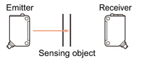
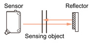
Thru-beam type and retroreflective type sensors
The setting distance must be equal to or less than the specified sensing range.
The sensors may be operable at a setting distance longer than the rated sensing range, but reliable operation cannot be guaranteed. Further, in a dirty or dusty environment, the setting should provide margin for beam intensity reduction.
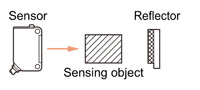
Reflective type sensors
The sensing range given in the specifications is for the standard sensing object.
Since the actual sensing distance differs with the size, color, surface condition, etc., of the sensing object, set the sensor giving enough margin for these differences.
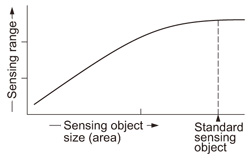
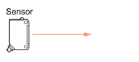
<Change of sensing range with sensing object size>
|
The bigger the sensing object size, the larger the quantity of light reflected, which increases the sensing range. |
 |
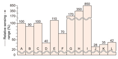
<Change of sensing range with sensing object> (Diffuse reflective type sensors)
|
|
|
The above mentioned relative sensing range for different sensing objects has been given taking the sensing range for white non-glossy paper as 100. The values are given for reference, and would vary slightly with the type of photoelectric sensor, sensing object size, etc.
Mounting
Mutual interference
If sensors are mounted adjacently, they may affect each other's operation (mutual interference). The following countermeasures are necessary to prevent it.
Countermeasure(1) : Use sensors having interference prevention function.
When sensors having the interference prevention function are used, sensors can be mounted close together.
Countermeasure(2) : Use interference prevention filters.
|
Interference prevention filters (optional) are available for CX-411□, NX5-M10RA and NX5-M10RB. |
<CX-411□> 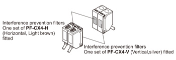 |
Countermeasure(3) : Increase the separation distance.
Find out the operating point ℓ1 on the parallel deviation diagram or the sensing field diagram for the setting distance L1. Separate sensors by 2 x ℓ1 or more.
(However, it is required that the emitter and receiver face each other and are installed in a direct line.)
|
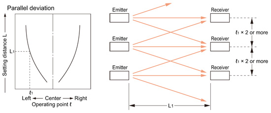
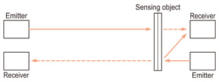
Countermeasure(4) : Place the emitter and the receiver alternately. (Thru-beam type sensors only)
|
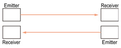
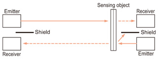
With this arrangement, if a sensing object comes near the sensors, the beam reflected from the sensing object may enter the receiver as shown below. In this case, countermeasures, such as placing a shield between the emitter and the receiver are necessary.
|
Placing a shield
|
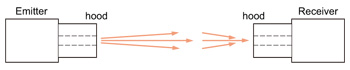
Countermeasure(5) : Narrow the light beam with a hood or a slit mask. (Thru-beam type sensors only)
|
Influence of surroundings
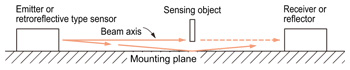
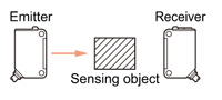
<Thru-beam type and retroreflective type sensors>
If a thru-beam type sensor, or a retroreflective type sensor is mounted on a flat shiny plane, the emitted beam may not be interrupted by a sensing object because some amount of the emitted beam passes through the gap between the sensing object and the plane, gets reflected from the plane, and enters the receiver.
|
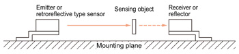
Countermeasure(1) : Increase distance from the mounting plane.
|
Countermeasure(2) : Place light barriers on the mounting plane.
|
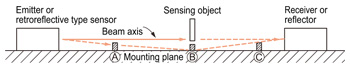
Place light barriers at (A), (B) and (C) to prevent reflection.
Countermeasure(3) : Paint the mounting plane in non-glossy black color.
Effect of mounting plane
<Reflective type sensors>
If a reflective type sensor is mounted on a rough plane, scatteredly reflected beam returns to the sensor.
This causes the hysteresis to increase or the sensor to always remain in the light received condition.
|

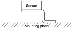
Countermeasure(1) : Increase distance from the mounting plane.
|
Countermeasure(2) : Paint the mounting plane in non-glossy black color.
Influence of background
If there is a wall, etc., behind the sensing object, the sensor operation may be affected.
Countermeasures
|
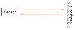 |
(However, the specular background should be a plane surface, directly facing the sensor. A spherical or curved background may be detected.)
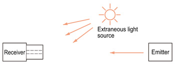
Influence of extraneous light
Most of the sensors use modulated beam highly immune to sunlight or ordinary fluorescent light. However, intense light or light from inverter fluorescent lamps may affect the sensor operation.
Countermeasure(1) : Tilt the beam axis so that the receiver is not directly facing the extraneous light source.
|
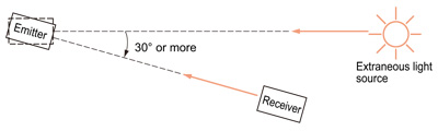
The incident angle and wavelength of the sunlight vary depending on the seasons, time of day, or other reasons. Thus, the influence that the sunlight has on sensors changes. For this reason, make sure to confirm that a malfunction does not occur with actual sensors before use.
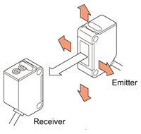
Countermeasure(2) : Attach a hood on the receiver.
|
Beam alignment (Thru-beam type and retroreflective type sensors)
|
 |
Perform the beam alignment with a retroreflective type sensor, similarly. Normally, the reflector angle can be set roughly, but the sensor angle must be precisely adjusted.
| Caution | : | The directional characteristics of photoelectric sensors can vary, so please be sure that you can adjust the beam axis using mounting brackets, etc. upon use. |
|---|
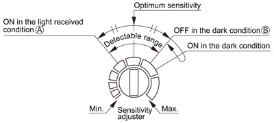
Sensitivity adjustment
Follow the procedure given below while noticing the operation indicator.
| 1 | : | In the light received condition, turn the sensitivity adjuster slowly and confirm the point (A) where the sensor enters the "Light" state operation. |
|---|---|---|
| 2 | : | In the dark condition, turn the sensitivity adjuster further clockwise until the sensor enters the "Light" state operation and then bring it back to confirm point (B) where the sensor just returns to the "Dark" state operation. (If the sensor does not enter the "Light" state operation even when the sensitivity adjuster is turned fully clockwise, this extreme position is point (B).) |
| 3 | : | The position at the middle of points (A) and (B) is the optimum sensing position. (Turn the adjuster with a slot screwdriver. The adjuster may be damaged if it is turned beyond its limit with excessive force.) |
|
| Type | Light received condition | Dark condition | ||
|---|---|---|---|---|
| Thru-beam | Presence detection | 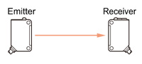 |
 |
|
| Light intensity detection | 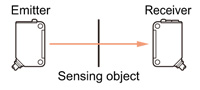 |
 |
||
| Retroreflective | Presence detection | 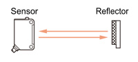 |
 |
|
| Light intensity detection | 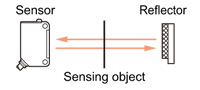 |
 |
||
| Reflective | Presence detection | 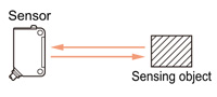 |
 |
|
| Mark sensing | Red beam | 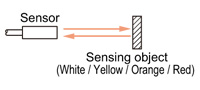 |
 |
|
| Green beam | 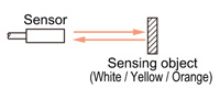 |
 |
||
For models equipped with auto sensitivity setting function, sensitivity adjustment is performed with a single touch of a button without the sensitivity adjustment described above.
Color discrimination during mark sensing
Color mark sensing
Marks can be sensed with mark sensor LX-100 series or color fiber sensor FZ-10 series, mark sensor or fiber sensor.
LX-100 series
<When the mark mode is set>
The optimal light source is automatically selected from the 3 colors of the R, G, B LEDs so that the contrast between the mark and base becomes the largest. This makes detection more stable.
<When the color mode is set>
The color mode utilizes all the R, G, B LEDs and detects the reflected light by calculating the R, G, B ratio. Thus, high precision detection is possible by sensing only the mark color that teaching was performed on.
FZ-10 series
The FZ-10 series uses red, green and blue LEDs to identify a color by its three color components. Hence, it is able to discriminate even minute color differences.
Mark sensors, Fiber sensors
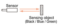
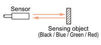
For mark sensors and fiber sensors, the color combinations of the mark and the background which can be discriminated, depending on the color of the light source, are as given in the table below.
| Mark color | White | Yellow | Orange | Red | Green | Blue | Black |
|---|---|---|---|---|---|---|---|
| Background color | |||||||
| White | - | (B) | (B) | (G)(B) | (R)(G)(B) | (R)(G)(B) | (R)(G)(B) |
| Yellow | (B) | - | (G) | (G) | (R)(G)(B) | (R)(G)(B) | (R)(G)(B) |
| Orange | (B) | (G) | - | (G)(B) | (R)(G)(B) | (R)(G)(B) | (R)(G)(B) |
| Red | (G)(B) | (G) | (G)(B) | - | (R) | (R)(B) | (R)(B) |
| Green | (R)(G)(B) | (R)(G)(B) | (R)(G)(B) | (R) | - | (B) | (B) |
| Blue | (R)(G)(B) | (R)(G)(B) | (R)(G)(B) | (R)(B) | (B) | - | (B) |
| Black | (R)(G)(B) | (R)(G)(B) | (R)(G)(B) | (R)(B) | (B) | (B) | - |
| (R) | : | Red LED type |
|---|---|---|
| (G) | : | Green LED type |
| (B) | : | Blue LED type |
Other precautions
- Our products have been developed / produced for industrial use only.
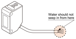
- Although the protection degree is specified for the sensor including the cable, the cable end is not waterproof and is not covered by the protection specified. Hence, make sure that water does not seep in from the cable end.
- Make sure that the power supply is off while wiring.
- Verify that the supply voltage variation is within the rating.。
- If power is supplied from a commercial switching regulator, ensure that the frame ground (F.G.) terminal of the power supply is connected to an actual ground.
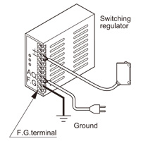
- In case noise generating equipment (switching regulator, inverter motor, etc.) is used in the vicinity of this product, connect the frame ground (F.G.) terminal of the equipment to an actual ground.
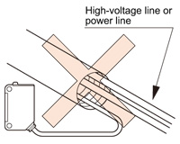
- Do not run the wires together with high-voltage lines or power lines or put them in the same raceway. This can cause malfunction due to induction.
- Avoid dust, dirt, and steam.
- Take care that the sensor does not come in direct contact with water, oil, grease or organic solvents, such as, thinner, etc.
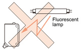
- Take care that the sensor is not directly exposed to fluorescent lamp from a rapid-starter lamp or a high frequency lighting device, as it may affect the sensing performance.
- These sensors are only for indoor use.
- Make sure that stress by forcible bend or pulling is not applied directly to the sensor cable joint.
- The usage environment should be within the ranges described in the specifications. In addition, the thru-beam type specifications for the emitter and receiver were measured under the same environment.
Use sensors within the range shown in the white part of the ambient temperature / humidity graph below and also within the certified ambient temperature and humidity range of each product. When using sensors within the range shown in the diagonal line shaded part of the graph, there is a possibility that condensation may occur depending on changes in the ambient temperature.
Please be careful not to let this happen.
Furthermore, pay attention that freezing does not occur when using below 0 ℃ +32 ℉. Please avoid condensation and freezing when storing the product as well.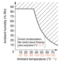
Related Products
Download
- photoelectric_e.pdf

|
BY EMAIL
- U.S.A.
- +1-800-344-2112
- Europe
- +49-89-45354-1000
- China
- +86-10-59255988
- Singapore
- +65-6299-9181


Requests to customers (Automation Control Components & Industrial Device) [Excluding specific product]
Requests to customers (Automation Control Components & Industrial Device) [For specific product]
Requests to customers (FA Sensors & Components [Excluding motors])
Requests to customers (Dedicated to industrial motors)
- COMPONENTS & DEVICES
- FA SENSORS & COMPONENTS
- Fiber Sensors
- Photoelectric Sensors / Laser Sensors
- Micro Photoelectric Sensors
- Light Curtains / Safety Components
- Area Sensors
- Inductive Proximity Sensors
- Particular Use Sensors
- Sensor Options
- Wire-Saving Systems
- Programmable Controllers / Interface Terminal
- Human Machine Interface
- Pressure Sensors / Flow Sensors
- Measurement Sensors
- Static Control Devices
- Laser Markers / 2D Code Readers
- Machine Vision System
- Energy Management Solutions
- Timers / Counters / FA Components
- MOTORS
![]()