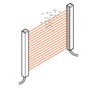
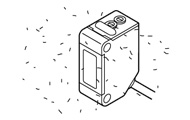
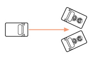
Self-diagnosis function
The sensor diagnoses the incident light intensity, and if it is reduced due to dust or dirt, or beam misalignment, a visual indication and/or an output is generated.
Dirt |
 |
|
Beam misalignment |
 |
|
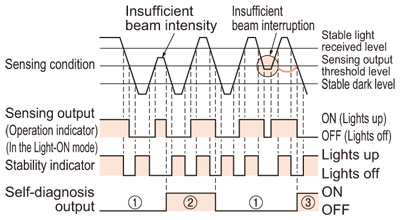
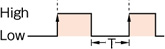
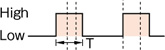
Time chart
| (1) |
: |
The self-diagnosis output transistor stays in the "OFF" state during stable sensing. |
| (2) |
: |
When the sensing output changes, if the incident light intensity does not reach the stable light received level or the stable dark level, the self-diagnosis output becomes ON.
Further, the self-diagnosis output changes state when the sensing output changes from Light to Dark state.
(It is not affected by the operation mode switch.) |
| (3) |
: |
In case of insufficient beam interruption, there will be a time lag before the self-diagnosis output turns ON. |
- Since the time chart differs with the sensor model.
- The SF4B-C series,SF4B series, SF4C series, BSF4-AH80, SF2B series, SF2C series etc., have a self-diagnosis function for the internal circuitry besides the above mentioned self-diagnosis function for the light incident intensity.
Return to top
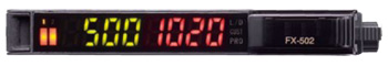
Light intensity monitor
Incident light intensity can be displayed numerically or by an LED array.
FX-500 / FX-100 / FX-300 / FX-410 series,
FX-301-F, LS series, LX-100 series
Incident light intensity can be shown on a digital display (4 digit LED or LCD).
(e.g.) FX-500 series |
 |
|
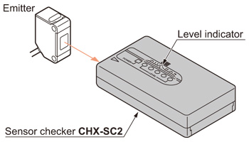
Infrared or red beam type of thru-beam photoelectric sensors
Using the optional sensor checker CHX-SC2, the incident light intensity can be checked audio-visually.
Return to top
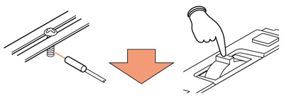
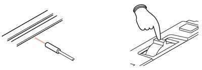
Automatic sensitivity (threshold value) setting
Sensitivity (threshold value) setting is done simply by pressing a button.
Press the jog switch (Note) with the object in front of the fiber. |
 |
|
Press the jog switch (Note) without the object. |
 |
|
| Note : | The FX-300 series and LS series are equipped with a jog switch.
The FX-500 series, FX-100 series, and LX-100 series use button operations. |
|---|
The FX-500 series, FX-100 series, FX-300 series, LS series and LX-100 series feature a full autoteaching function by which sensitivity setting can be done on a moving object without stopping the assembly line. Further, in case of the FZ-10 series and SU-7 series, sensitivity setting is done by using a button switch.
Return to top
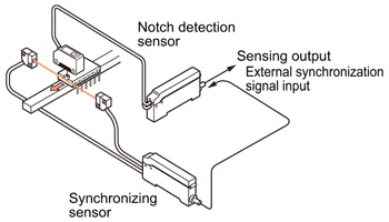
External synchronization function
The timing of sensing can be controlled.
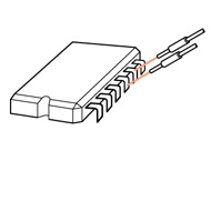
Application
Checking orientation of IC |
 |
|
Return to top
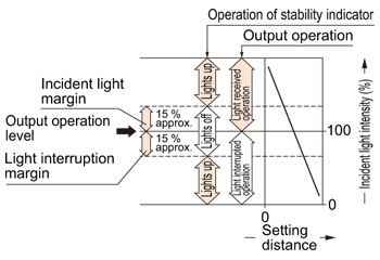
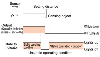
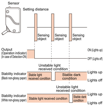
Stability indicator
The stability indicator (green) lights up when the incident light intensity has sufficient margin with respect to the operation level. If the incident light intensity level is such that the stability indicator lights up, stable sensing can be done without the light received operation and the light interrupted operation being affected by a change in ambient temperature or supply voltage.
- In case of the NA2-N series, NA1-PK5 series, NA1-5 series and NA1-PK3 series, this is the stable incident beam indicator and lights up when the incident light margin is exceeded.
- The stability indicator (green) of the CX-440 series and EQ-500 series shows the safety margin of the setting distance.
- The stability indicator (green) of the EQ-30 series shows the safety margin of the incident light intensity, not that of the object distance.
Hence, the distance at which it lights up / off depends on the object reflectivity and is not at all related to the output operation. Do not use the sensor when the stability indicator is off (unstable light received condition), since the sensing will be unstable.
Return to top
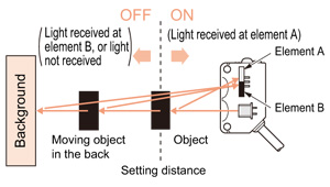
BGS / FGS functions
Depending on the positional relation between the background and the sensing object, either the BGS or FGS function will be selected.
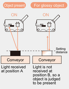
BGS (Background suppression)
The sensor judges that an object is present when light is received at position A of the light-receiving element (2-segment element).
This is useful if the object and background are far apart. The distance adjustment method is the same as the conventional adjustment method for adjustable range reflective type sensors.
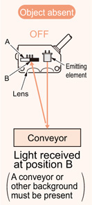
FGS (Foreground suppression)
The sensor judges that an object is present when no light is received at position B of the light-receiving element (2-segment element).
Accordingly, even objects that are glossy can be sensed. This is useful if the object and background are close together, or if the object being sensed is glossy.
OFF in this condition only |
 |
|
ON in all other conditions |
 |
|
Return to top
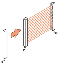
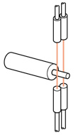
Interference prevention function
When several photoelectric sensors are mounted close together, mutual interference can be prevented by setting different emission frequencies. Interference prevention function by which the emission frequency can be changed by a switch or an interference prevention wire, or, automatic interference prevention function by which the frequency is automatically changed by the sensor are available.
Application
Checking orientation of workpiece |
 |
|
Detecting IC pins |
 |
|
Return to top
Timer function
The width of the output signal is controlled to match the connected device specifications.
ON-delay
| Function |
: |
Neglects short output signals. |
| Application |
: |
As only longer signals are extracted, this function is useful for detecting if
a line is clogged, or for sensing only objects taking a long time to travel. |
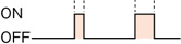
OFF-delay
| Function |
: |
Extends the output signal for a fixed period of time. |
| Application |
: |
This function is useful if the output signal is so short that the connected device cannot respond. |
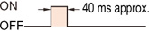
ONE SHOT
| Function |
: |
Outputs a fixed width signal upon sensing |
| Application |
: |
This function is useful when the input specifications of the connected device require a signal of fixed width. Of course, it is also useful for extending a short width signal to a desired width. |
The FX-500 series, FX-305(P) is equipped with an ON-delay / OFF-delay timer that allows you to use ON and OFF-delay simultaneously as well as an ON-delay / ONE SHOT timer enabling a simultaneous ON-delay and ONE SHOT.
Return to top
Automatic sensitivity compensation function
The sensitivity is adjusted according to the setting distance to maintain the optimum sensitivity.
The sensitivity is reduced if the emitter and the receiver are brought closer.
The sensitivity is increased in case of dust or dirt.
Return to top
Test input (emission halt input) function
The emission can be stopped by an external test input.
Application
Start-up inspection |
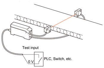 |
|
Time chart |
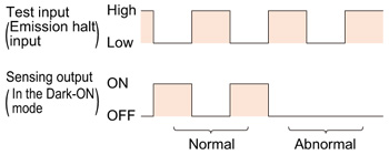 |
|
When several sensors are arrayed in a line, this function can also be used for mutual interference prevention by controlling the beam emission in a cyclic manner.
| Note : | Set the operation setting to light-ON for FX-502(P). |
|---|

 Business
> Industrial Devices
> Automation Controls Top
> Service & Support
> FA Technical Support
> Technical Guide (FA Sensors)
> Photoelectric Sensors
> Functions
Business
> Industrial Devices
> Automation Controls Top
> Service & Support
> FA Technical Support
> Technical Guide (FA Sensors)
> Photoelectric Sensors
> Functions