[System Maintenance Notice]
Due to ongoing system maintenance, the site search and specification search functions are temporarily unavailable. We apologize for any inconvenience this may cause and appreciate your understanding.

 Business
> Industrial Devices
> Automation Controls Top
> Components & Devices
> Relays / Couplers
> High-capacity DC Cutoff Relay
> HE-V Relays
> Rating/Performance
Business
> Industrial Devices
> Automation Controls Top
> Components & Devices
> Relays / Couplers
> High-capacity DC Cutoff Relay
> HE-V Relays
> Rating/Performance
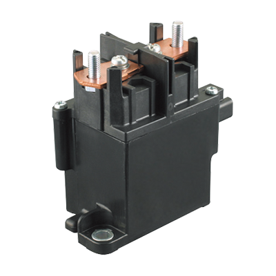
HE-V Relays
-
Lineup
-
 EP Relays
High capacity of Max. 1,000 V DC Cut-off possible
EP Relays
High capacity of Max. 1,000 V DC Cut-off possible
-
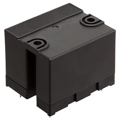 HE-V Relays
Max. 1,000 V DC, 20 A cut-off possible, High capacity DC power relays
HE-V Relays
Max. 1,000 V DC, 20 A cut-off possible, High capacity DC power relays
-
- CAD data Catalogs/Datasheets
- FAQ
|
Coil data
- Operating characteristics such as 'Operate voltage' and 'Release voltage' are influenced by mounting conditions, ambient temperature, etc.
Therefore, please use the relay within ±5% of rated coil voltage. - 'Initial' means the condition of products at the time of delivery.
| Rated coil voltage |
Operate voltage* (at 20°C) |
Release voltage* (at 20°C) |
Rated operating current (±10%, at 20°C) |
Coil resistance (±10%, at 20°C) |
Rated operating power |
Max. allowable voltage (at 55°C) |
|---|---|---|---|---|---|---|
| 6 V DC | Max. 70% V of rated coil voltage (Initial) |
Min. 5% V of rated coil voltage (Initial) |
320 mA | 18.8 Ω | 1,920 mW | 110% V of rated coil voltage |
| 9 V DC | 213 mA | 42.2 Ω | ||||
| 12 V DC | 160 mA | 75 Ω | ||||
| 15 V DC | 128 mA | 117 Ω | ||||
| 24 V DC | 80 mA | 300 Ω |
| * | square, pulse drive |
|---|
Specifications
| Item | Specifications | |
|---|---|---|
| Contact data | Contact arrangement | 2 Form A |
| Contact resistance (initial) |
Max. 100 mΩ (by voltage drop 6 V DC 1 A) Max. 3 mΩ (by voltage drop 6 V DC 20 A, reference value) |
|
| Contact material | AgNi type | |
| Contact rating (resistive) |
20 A 800 V DC, 25 A 600 V DC (at contact connected in series) 20 A 400 V DC (at 1 Form A contact only) |
|
| Max. switching voltage | 1,000 V DC | |
| Max. switching current | 25 A | |
| Min. switching load (reference value) *1 |
100 mA 5 V DC | |
| Insulation resistance (initial) | Min. 1,000 MΩ (at 1,000 V DC, Measured portion is the same as the case of dielectric strength.) |
|
| Short current (initial) | Max. 300 A 1 ms (reference value) | |
| Dielectric strength (initial) |
Between open contacts |
2,000 Vrms for 1 min (detection current: 10 mA) |
| Between contact sets |
4,000 Vrms for 1 min (detection current: 10 mA) | |
| Between contact and coil |
5,000 Vrms for 1 min (detection current: 10 mA) | |
| Surge withstand voltage (initial)*2 | Between contact and coil |
10,000 V |
| Coil holding voltage *3 | 33 to 110% V (at -40 to +55°C: contact carrying current 25 A) 33 to 60% V (at -40 to +85°C: contact carrying current 25 A) |
|
| Time characteristic (initial) |
Operate time | Max. 30 ms at rated coil voltage (at 20°C, without bounce) |
| Release time | Max. 10 ms at rated coil voltage (at 20°C, without bounce, without diode) | |
| Shock resistance |
Functional | 98 m/s2 (half-sine shock pulse: 11 ms, detection time: 10 μs) |
| Destructive | 980 m/s2 (half-sine shock pulse: 6 ms) | |
| Vibration resistance | Functional | 10 to 55 Hz (at double amplitude of 1 mm, detection time: 10 μs) |
| Destructive | 10 to 55 Hz (at double amplitude of 1.5 mm) | |
| Expected life | Mechanical life | Min. 106 ope. (switching frequency: at 180 times/min) |
| Conditions | Conditions for usage, transport and storage *4 |
Ambient temperature: -40 to +55°C (when coil holding voltage is 33% to 110% of rated coil voltage) -40 to +85°C (when coil holding voltage is 33% to 60% of rated coil voltage) Humidity: 5 to 85% RH (Avoid icing and condensation) |
| Unit weight | Approx. 120 g | |
| *1 | This value can change due to the switching frequency, environmental conditions, and desired reliability level, therefore it is recommended to check this with the actual load. |
|---|---|
| *2 | Wave is standard shock voltage of ±1.2 x 50 µs according to JEC-212-1981. |
| *3 | Coil holding voltage is the coil voltage after 100 ms following application of the nominal coil voltage. |
| *4 | For ambient temperature, please read "GUIDELINES FOR RELAY USAGE". |
Expected electrical life
1. Contact connected in series
Conditions: at 20°C (L/R ≦ 1 ms), switching frequency ON : OFF = 1 s : 9 s
| Load | Switching capacity | Number of operations |
|---|---|---|
| Resistive load | 20 A 600 V DC | Min. 10 x 103 ope. |
| 20 A 800 V DC | Min. 103 ope. | |
| 25 A 600 V DC | Min. 6 x 10³ ope. | |
| Overload | 20 A 1,000 V DC | Min. 10 ope. |
| Reverse direction | -20 A 400 V DC | Min. 103 ope. |
| Inrush resistance current | 40 A 800 V DC | Min. 103 ope. |
2. 1 Form A contact only
Conditions: at 20°C (L/R ≦ 1 ms), switching frequency ON : OFF = 1 s : 9 s
| Load | Switching capacity | Number of operations |
|---|---|---|
| Resistive load | 20 A 300 V DC | Min. 10 x 103 ope. |
| 20 A 400 V DC | Min. 103 ope. | |
| Overload | 20 A 500 V DC | Min. 10 ope. |
| Reverse direction | -20 A 200 V DC | Min. 103 ope. |
| Inrush resistance current | 40 A 400 V DC | Min. 103 ope. |
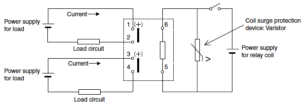
Recommended circuit
Positive polarity of load should be connected to pin 1 and pin 3, refer to the following circuit schematics.
1. Contact connected in series (BOTTOM VIEW)
|
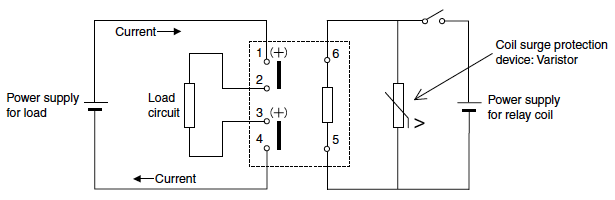
2. 1 Form A contact only (BOTTOM VIEW)
|
|
Related Information
BY EMAIL


Requests to customers (Automation Control Components & Industrial Device) [Excluding specific product]
Requests to customers (Automation Control Components & Industrial Device) [For specific product]
Requests to customers (FA Sensors & Components [Excluding motors])
Requests to customers (Dedicated to industrial motors)
- COMPONENTS & DEVICES
- FA SENSORS & COMPONENTS
- Fiber Sensors
- Photoelectric Sensors / Laser Sensors
- Micro Photoelectric Sensors
- Light Curtains / Safety Components
- Area Sensors
- Inductive Proximity Sensors
- Particular Use Sensors
- Sensor Options
- Wire-Saving Systems
- Programmable Controllers / Interface Terminal
- Human Machine Interface
- Pressure Sensors / Flow Sensors
- Measurement Sensors
- Static Control Devices
- Laser Markers / 2D Code Readers
- Machine Vision System
- Energy Management Solutions
- Timers / Counters / FA Components
- MOTORS
![]()