[System Maintenance Notice]
Due to ongoing system maintenance, the site search and specification search functions are temporarily unavailable. We apologize for any inconvenience this may cause and appreciate your understanding.

 Business
> Industrial Devices
> Automation Controls Top
> Components & Devices
> Relays / Couplers
> Interface Terminal
> RT-3 UNIT RELAY (PA-N relay type) /4-POINT TERMINAL (Without relay type)
> Rating/Performance
Business
> Industrial Devices
> Automation Controls Top
> Components & Devices
> Relays / Couplers
> Interface Terminal
> RT-3 UNIT RELAY (PA-N relay type) /4-POINT TERMINAL (Without relay type)
> Rating/Performance
RT-3 UNIT RELAY (PA-N relay type) /4-POINT TERMINAL (Without relay type)
-
Lineup
-
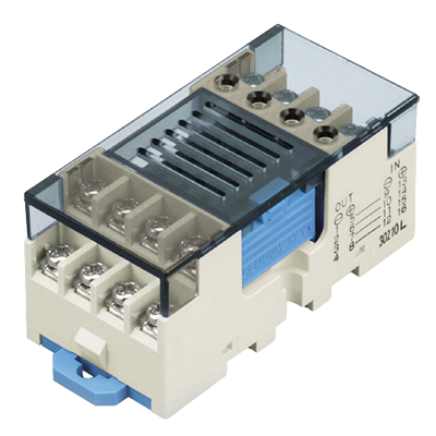 RT-3 UNIT RELAY (PA-N relay type) /4-POINT TERMINAL (Without relay type)
Mix mechanical relays and PhotoMOS in accordance with your application.
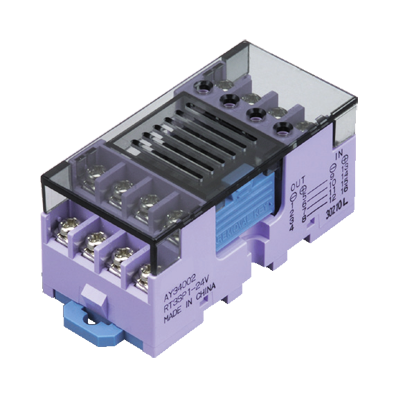
RT-3 UNIT RELAY (PA-N relay type) /4-POINT TERMINAL (Without relay type)
Mix mechanical relays and PhotoMOS in accordance with your application.
-
 RT-3 UNIT RELAY (PhotoMOS Power type) /4-POINT TERMINAL (Without relay type)
Slim, Space-saving, RT-3 Unit relay (Equipped with long-life PhotoMOS power type)
RT-3 UNIT RELAY (PhotoMOS Power type) /4-POINT TERMINAL (Without relay type)
Slim, Space-saving, RT-3 Unit relay (Equipped with long-life PhotoMOS power type)
-
- CAD data Catalogs/Datasheets
- FAQ
Rating
1.RT-3 Unit relay
1. Input ratings (per relay)
| Part No. | Rated input voltage | Input current (at rated input voltage) (at 20°C) |
Allowable variation of rated input voltage (-20 to +55°C) |
|---|---|---|---|
| AY32001 | 12 V DC | Approx. 10.7 mA (Relay 9.2 mA + LED 1.5 mA) | 12 V DC ± 10% |
| AY32002 | 24 V DC | Approx. 7.6 mA (Relay 4.6 mA + LED 3.0 mA) | 24 V DC ± 10% |
2. PA-N relay coil specifications (Reference value)
| Relay part No. |
Operate voltage (at 20°C) | Release voltage (at 20°C) | Coil resistance (±10%) (at 20°C) |
Rated operating power |
|---|---|---|---|---|
| APAN3112 | Max. 70% V of rated coil voltage (Initial) | Min. 5% V of rated coil voltage (Initial) | 1,309 Ω | 110 mW |
| APAN3124 | 5,236 Ω | 110 mW |
3. Output ratings (per relay)
| Specification | Item | Specifications |
|---|---|---|
| Contact data | Contact rating (resistive) | 3 A 250 V AC, 3 A 30 V DC |
| Max. switching power (resistive) | 750 VA (AC), 90 W (DC) | |
| Max. switching voltage | 250 V AC, 30 V DC | |
| Max. switching current | 3 A | |
| Min. switching load (reference value) | 100 μA 100 mV DC | |
| Expected life | Mechanical life | Min. 20 x 106 ope. (at 180 times/min) |
| Electrical life (resistive) | 3 A 250 V AC: Min. 30 x 103 ope. 3 A 30 V DC: Min. 30 × 103 ope. 2 A 250 V AC: Min. 100 × 103 ope. 2 A 30 V DC: Min. 100 × 103 ope. |
| * | Note: During 4-point simultaneous operation, the rating per point is also as shown above. |
|---|
2.4-point Terminal
1. Input ratings (per relay)
| Rated input voltage | Allowable variation of rated input voltage | Allowable input current |
|---|---|---|
| 12 V, 24 V DC | 12 V DC ± 10%, 24 V DC ± 10% | 0.2 A |
| * | The input voltage value above is the allowable current when no relay is installed. Please note that input voltage is determined by the type of relay installed. |
|---|
2. Input rating when PA-N relay installed (per relay, at 20°C)
| Type | Rated input voltage |
Operate voltage (Initial) | Release voltage (Initial) | Input current (during application of rated input voltage) |
|---|---|---|---|---|
| APAN3112 | 12 V DC | Max. 9.5 V DC (Relay max. 8.4 V + include diode max. 1.1 V) |
Min. 1.0 V DC (Relay min. 0.6 V + include diode min. 0.4 V) |
Approx. 10.7 mA (Relay 9.2 mA + LED 1.5 mA) |
| APAN3124 | 24 V DC | Max. 17.9 V DC (Relay max. 16.8 V + include diode max. 1.1 V) |
Min. 1.6 V DC (Relay min. 1.2 V + include diode min. 0.4 V) |
Approx. 7.6 mA (Relay 4.6 mA + LED 3.0 mA) |
3. Input rating when PhotoMOS Power voltage sensitive type installed (per relay, at 25°C)
| Type | Rated input voltage |
Operate voltage (Initial) | Release voltage (Initial) | Input current (during application of rated input voltage) |
|---|---|---|---|---|
| AQZ∗0∗D | 12 V, 24 V DC | Max. 5.1 V DC (Relay max. 4.0 V + include diode max. 1.1 V) |
Min. 1.2 V DC (Relay min. 0.8 V + include diode min. 0.4 V) |
Approx. 10.0 mA (Relay 7.0 mA + LED 3.0 mA) |
4. Output rating (per relay)
| Allowable load voltage | Allowable load current |
|---|---|
| 600 V (DC), 600 V (AC peak value) | 3 A |
| * | The value above is the allowable value when no relay is installed. Please note that limitations apply to the load voltage and current depending on the type of relay installed. |
|---|
5. Output rating when PA-N relay installed (per relay, at 20°C)
| Specification | Item | Specifications |
|---|---|---|
| Contact data | Contact rating (resistive) | 3 A 250 V AC, 3 A 30 V DC |
| Max. switching power (resistive) | 750 VA (AC), 90 W (DC) | |
| Max. switching voltage | 250 V AC, 30 V DC | |
| Max. switching current | 3 A | |
| Min. switching load (reference value) | 100 μA 100 mV DC | |
| Expected life | Mechanical life | Min. 20 x 106 ope. (at 180 times/min) |
| Electrical life (resistive) | 3 A 250 V AC, 3 A 30 V DC: Min. 30 × 103 ope. 2 A 250 V AC, 2 A 30 V DC: Min. 100 × 103 ope. |
| * | During 4-point simultaneous operation, the rating per point is also as shown above. |
|---|
6. Output rating when PhotoMOS Power voltage sensitive type installed (per relay, at 25°C)
| Mountable relays | Maximum load voltage (DC, AC peak value) |
Continuous load current (DC, AC peak value) |
Mountable relays | Maximum load voltage (DC, AC peak value) |
Continuous load current (DC, AC peak value) |
||
|---|---|---|---|---|---|---|---|
| Type | Part No. | Type | Part No. | ||||
| DC only | AQZ102D | 60 V | 1.80 A | AC, DC dual use |
AQZ202D | 60 V | 1.350 A |
| AQZ105D | 100 V | 1.15 A | AQZ205D | 100 V | 0.900 A | ||
| AQZ107D | 200 V | 0.55 A | AQZ207D | 200 V | 0.450 A | ||
| AQZ104D | 400 V | 0.30 A | AQZ204D | 400 V | 0.225 A | ||
| * | During 4-point simultaneous operation, the rating per point is also as shown above. Please use a load current that is within the range of the data given below in “REFERENCE DATA Load current vs. ambient temperature characteristics”. |
|---|
Specifications
RT-3 Unit relay/4-point Terminal
| Item | Specifications | Condition | |
|---|---|---|---|
| Dielectric strength (Initial) |
Between input and output | 2,000 Vrms | for 1 min |
| Between different terminals (between relays, both ways) |
1,500 Vrms | for 1 min | |
| Insulation resistance | Min. 100 MΩ (Measured portion is the same as the case of dielectric strength.) | Using 500 V DC megger | |
| Shock resistance |
Destructive | Min. 196 m/s2 | In vertical, horizontal and longitudinal directions |
| Functional | Min. 98 m/s2 | In vertical, horizontal and longitudinal directions | |
| Vibration resistance |
Destructive | 10 to 55 Hz at double amplitude of 1 mm | In vertical, horizontal and longitudinal directions |
| Functional | 10 to 55 Hz at double amplitude of 1 mm | In vertical, horizontal and longitudinal directions | |
| Use condition | Ambient temperature | -20 to +55°C | Avoid icing and condensation |
| Ambient humidity | 35 to 85% RH | Avoid condensation | |
| Storage temperature | -30 to +80°C | Avoid icing and condensation | |
| Terminal screw fasten torque | 0.3 to 0.5 N·m (3 to 5 kgf·cm) | ||
| Coil surge absorber | Diode (1 A, 400 V) | ||
| Cross connection protecting diode | 1 A, inverse voltage 400 V | ||
| Unit weight | Approx. 100 g | ||
| *1 | Dielectric strength and insulation resistance are initial values. |
|---|---|
| *2 | Condensing occurs when the unit relay is exposed to sudden temperature change in a high temperature and high humidity atmosphere. This may cause some troubles like insulation failure of the socket or the PC board. Take care under this condition. |
| *3 | Below 0°C, condensing water can freeze and cause socket contact failures and other problems. Take care under this condition. |
Reference data
|
||||||||||
BY EMAIL


Requests to customers (Automation Control Components & Industrial Device) [Excluding specific product]
Requests to customers (Automation Control Components & Industrial Device) [For specific product]
Requests to customers (FA Sensors & Components [Excluding motors])
Requests to customers (Dedicated to industrial motors)
- COMPONENTS & DEVICES
- FA SENSORS & COMPONENTS
- Fiber Sensors
- Photoelectric Sensors / Laser Sensors
- Micro Photoelectric Sensors
- Light Curtains / Safety Components
- Area Sensors
- Inductive Proximity Sensors
- Particular Use Sensors
- Sensor Options
- Wire-Saving Systems
- Programmable Controllers / Interface Terminal
- Human Machine Interface
- Pressure Sensors / Flow Sensors
- Measurement Sensors
- Static Control Devices
- Laser Markers / 2D Code Readers
- Machine Vision System
- Energy Management Solutions
- Timers / Counters / FA Components
- MOTORS
![]()