[System Maintenance Notice]
Due to ongoing system maintenance, the site search and specification search functions are temporarily unavailable. We apologize for any inconvenience this may cause and appreciate your understanding.
 Business
> Industrial Devices
> Automation Controls Top
> Components & Devices
> Relays / Couplers
> /ac/ae/control/relay/safety/index.jsp?c=search">Safety Relays
>
> Cautions For Use
Safety Structure of SF Relays
This SF relay design ensures that subsequent operations shut down and can automatically return to a safe state when the SF relay suffers overloading and other circuit abnormalities (unforeseen externally caused circuit or device breakdowns, end of life incidents, and noise, surge, and environmental influences) owing to contact welding, spring fusion or, in the worst-case scenario, relay breakdown (coil rupture, faulty operation, faulty return, and fatigue and breakage of the operating spring and return spring), and even in the event of end of life.
| Structure | Operation | |||
|---|---|---|---|---|
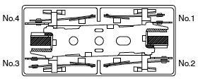
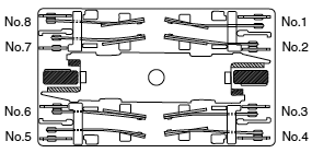
| 1. Forced operation method (2 Form A 2 Form B, 4 Form A 4 Form B types) |
|
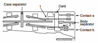
Even when one contact is welded closed, the other maintains a gap of greater than 0.5 mm .020 inch. In the diagram on the left, the lower contact “b” have welded but the upper contact “a” maintain at a gap of greater than 0.5 mm .020 inch. Subsequent contact movement is suspended and the weld can be detected |
||
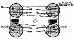
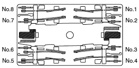
| 2. Independent operation method (4 Form A 4 Form B type) |
|
Enables design of safety circuits that allow weld detection and return at an early stage. As shown at the top right of the diagram on the left, if the external N.O. contact welds, a 0.5 mm .020 inch gap is maintained. Each of the other contacts returns to N.O. because the coil is no longer energized. |
||
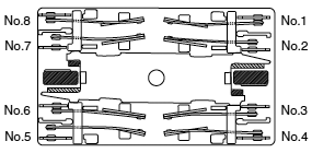
| 3. Separate chamber method (2 Form A 2 Form B, 4 Form A 4 Form B types) |
|
Prevents shorting and fusing of springs and spring failure owing to short-circuit current. As shown on the diagram on the left, even if the operating springs numbered 1 and 2 there is no shorting between “a” and “b” contacts. |
||
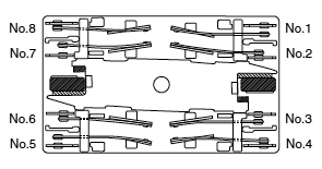
| 4. 2 Form A 2 Form B contact 4 Form A 4 Form B contact |
Structure with independent COM contact of 2 Form A 2 Form B and 4 Form A 4 Form B contacts. | Independent COM enables differing pole circuit configurations. This makes it possible to design various kinds of control circuits and safety circuits. |
The Operation of SF Relays (when contacts are welded)
SF relays work to maintain a normal operating state even when the contact welding occur by overloading or short-circuit currents. It is easy to make weld detection circuits and safety circuits in the design to ensure safety even if contacts weld.
1) 2 Form A 2 Form B type
Form “b” Contact Weld
If the form “b” contact (No. 1 and 3) welds, the armature becomes non-operational, the contact gaps at the three form “a” contacts are maintained at greater than 0.5 mm .020 inch. Reliable isolation is thus ensured.
|
→ |
|
Example: If the No. 1 contact welds
Each of the three form “a” contacts (No. 2 and 4) maintain a gap of greater than 0.5 mm .020 inch.
Form “a” Contact Weld
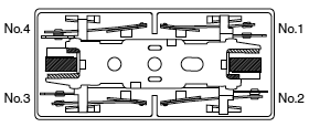
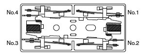
When the form “a” contacts (No. 2 or 4) weld, the armature remains in a non-returned state and the contact gap at the two form “b” contact is maintained at greater than 0.5 mm .020 inch. Reliable isolation is thus ensured.
|
→ |
|
Example: If the No. 2 contact welds.
The two form “b” contact (No. 1 or 3) maintains a gap of greater than 0.5 mm .020 inch.
Contact Operation Table
|
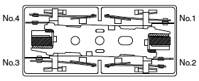
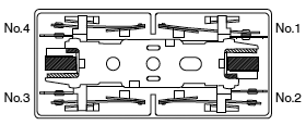
| Contact No. | No.1 | No.2 | No.3 | No.4 |
|---|---|---|---|---|
| Terminal No. | 11-12 | 7-8 | 5-6 | 9-10 |
The table below shows the state of the other contacts when the current through the welded form “a” contact is 0 V and the rated voltage is applied through the form “b” contact.
| State of other contacts | |||||
|---|---|---|---|---|---|
| 1 | 2 | 3 | 4 | ||
| Welded terminal No. | 1 | — | >0.5 | >0.5 | |
| 2 | >0.5 | — | >0.5 | ||
| 3 | >0.5 | — | >0.5 | ||
| 4 | >0.5 | >0.5 | — | ||
>0.5: contact gap is kept at min. 0.5 mm .020 inch
Empty cells: either closed or open
| * |
Contact gaps are shown at the initial state. If the contacts change state owing to loading/breaking it is necessary to check the actual loading. |
2)4 Form A 4 Form B type
Internal Contacts Weld
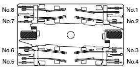
When internal contacts (No. 2, No. 3, No. 6 or No. 7) are welded, the armature becomes non-operational and the four form “a” contact gaps are maintained at 0.5 mm .020 inch or greater. Reliable cut-off is thus ensured.
|
→ |
|
Example: If the No. 2 contact welds.
Each of the four form “a” contacts (No. 1, 3, 5, and 7) maintains a gap of greater than 0.5 mm .020 inch.
External Contacts Weld
When external contacts (No. 1, No. 4, No. 5 or No. 8) are welded, gaps of 0.5 mm .020 inch and greater are maintained between adjacent contacts and other contacts operate normally by the coil being non-energized.
|
→ |
|
Example 1: If the No. 1 contact welds.
The adjacent No. 2 contact maintains a gap of greater than 0.5 mm .020 inch. The other contacts, because the coil is not energized, return to their normal return state; each of form “a” contacts (No. 3, 5, and 7) maintains a contact gap of greater than 0.5 mm .020 inch; each of the form “b” contacts (No. 4, 6, and 8) return to a closed state.
Example 2: If external connections are made in series.
Even if one of the contacts welds, the other contacts operate independently and the contact gaps are maintained at greater than 0.5 mm .020 inch.
|
Contact Operation Table
|
| Contact No. | No.1 | No.2 | No.3 | No.4 | No.5 | No.6 | No.7 | No.8 |
|---|---|---|---|---|---|---|---|---|
| Terminal No. | 20-19 | 12-11 | 8-7 | 16-15 | 13-14 | 5-6 | 9-10 | 17-18 |
The table below shows the state of the other contacts when the current through the welded form “a” contact is 0 V and the rated voltage is applied through the form “b” contact.
| Contact No. | State of other contacts | ||||||||
|---|---|---|---|---|---|---|---|---|---|
| 1 | 2 | 3 | 4 | 5 | 6 | 7 | 8 | ||
| Welded terminal No. | 1 | — | >0.5 | >0.5 | ≠ | >0.5 | ≠ | >0.5 | ≠ |
| 2 | >0.5 | — | >0.5 | >0.5 | >0.5 | ||||
| 3 | >0.5 | — | >0.5 | >0.5 | >0.5 | ||||
| 4 | ≠ | >0.5 | >0.5 | — | ≠ | >0.5 | ≠ | >0.5 | |
| 5 | >0.5 | ≠ | >0.5 | ≠ | — | >0.5 | >0.5 | ≠ | |
| 6 | >0.5 | >0.5 | >0.5 | — | >0.5 | ||||
| 7 | >0.5 | >0.5 | >0.5 | — | >0.5 | ||||
| 8 | ≠ | >0.5 | ≠ | >0.5 | ≠ | >0.5 | >0.5 | — | |
>0.5: contact gap is kept at min. 0.5 mm .020 inch
≠: contact closed
Empty cells: either closed or open
| * |
Contact gaps are shown at the initial state. If the contacts change state owing to loading/breaking it is necessary to check the actual loading. |
BY EMAIL
Requests to customers (Automation Control Components & Industrial Device) [Excluding specific product]
Requests to customers (Automation Control Components & Industrial Device) [For specific product]
Requests to customers (FA Sensors & Components [Excluding motors])
Requests to customers (Dedicated to industrial motors)
- COMPONENTS & DEVICES
- FA SENSORS & COMPONENTS
- Fiber Sensors
- Photoelectric Sensors / Laser Sensors
- Micro Photoelectric Sensors
- Light Curtains / Safety Components
- Area Sensors
- Inductive Proximity Sensors
- Particular Use Sensors
- Sensor Options
- Wire-Saving Systems
- Programmable Controllers / Interface Terminal
- Human Machine Interface
- Pressure Sensors / Flow Sensors
- Measurement Sensors
- Static Control Devices
- Laser Markers / 2D Code Readers
- Machine Vision System
- Energy Management Solutions
- Timers / Counters / FA Components
- MOTORS


