[System Maintenance Notice]
Due to ongoing system maintenance, the site search and specification search functions are temporarily unavailable. We apologize for any inconvenience this may cause and appreciate your understanding.

 Business
> Industrial Devices
> Automation Controls Top
> Components & Devices
> Relays / Couplers
> Safety Relays
> SF-Y Relays
> Rating/Performance
Business
> Industrial Devices
> Automation Controls Top
> Components & Devices
> Relays / Couplers
> Safety Relays
> SF-Y Relays
> Rating/Performance
SF-Y Relays
-
Lineup
-
 SF Relays
Flat type Safety relay compliant with Safety standards
SF Relays
Flat type Safety relay compliant with Safety standards
-
 SF Relays Slim type
Slim type Safety relay compliant with Safety standards
SF Relays Slim type
Slim type Safety relay compliant with Safety standards
-
 SF Relays Double contact type
Flat type (double contact) Safety relay compliant with Safety standards
SF Relays Double contact type
Flat type (double contact) Safety relay compliant with Safety standards
-
 SF-M Relays
Flat type safety relays (1 Form A 1 Form B)
SF-M Relays
Flat type safety relays (1 Form A 1 Form B)
-
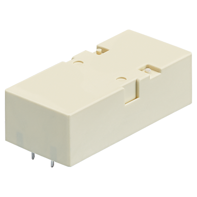
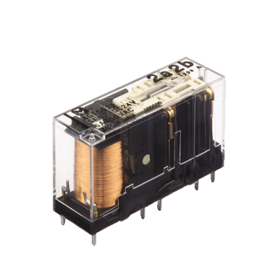
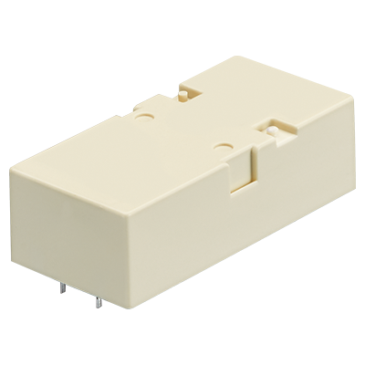
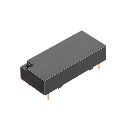
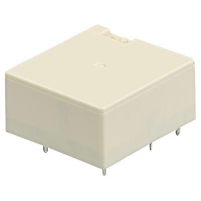 SF-Y Relays
Compact Flat type Safety relay compliant with European safety standards
SF-Y Relays
Compact Flat type Safety relay compliant with European safety standards
-
- CAD data Catalogs/Datasheets
- FAQ
|
Coil data
| Contact arrangement |
Rated coil voltage |
Operate voltage * (at 20°C) |
Release voltage * (at 20°C) |
Rated operating current (±10%, at 20°C) |
Coil resistance (±10%, at 20°C) |
Rated operating power |
Max. allowable voltage (at 60°C) |
|
|---|---|---|---|---|---|---|---|---|
| 4 poles | 2 Form A 2 Form B |
5 V DC | Max. 75% V of rated coil voltage (Initial) | Min. 15% V of rated coil voltage (Initial) | 134 mA | 38 Ω | 670 mW | 120% V of rated coil voltage |
| 12 V DC | 56 mA | 215 Ω | ||||||
| 16 V DC | 42 mA | 380 Ω | ||||||
| 18 V DC | 37 mA | 483 Ω | ||||||
| 21 V DC | 32 mA | 666 Ω | ||||||
| 24 V DC | 28 mA | 864 Ω | ||||||
| 3 Form A 1 Form B |
5 V DC | 134 mA | 38 Ω | |||||
| 12 V DC | 56 mA | 215 Ω | ||||||
| 16 V DC | 42 mA | 380 Ω | ||||||
| 18 V DC | 37 mA | 483 Ω | ||||||
| 21 V DC | 32 mA | 666 Ω | ||||||
| 24 V DC | 28 mA | 864 Ω | ||||||
| 6 poles | 4 Form A 2 Form B |
5 V DC | 134 mA | 38 Ω | ||||
| 12 V DC | 56 mA | 215 Ω | ||||||
| 16 V DC | 42 mA | 380 Ω | ||||||
| 18 V DC | 37 mA | 483 Ω | ||||||
| 21 V DC | 32 mA | 666 Ω | ||||||
| 24 V DC | 28 mA | 864 Ω | ||||||
| 5 Form A 1 Form B |
5 V DC | 134 mA | 38 Ω | |||||
| 12 V DC | 56 mA | 215 Ω | ||||||
| 16 V DC | 42 mA | 380 Ω | ||||||
| 18 V DC | 37 mA | 483 Ω | ||||||
| 21 V DC | 32 mA | 666 Ω | ||||||
| 24 V DC | 28 mA | 864 Ω | ||||||
Specifications
| Item | Specifications | ||||
|---|---|---|---|---|---|
| 4 poles | 6 poles | ||||
| Contact data | Contact arrangement | 2 Form A 2 Form B |
3 Form A 1 Form B |
4 Form A 2 Form B |
5 Form A 1 Form B |
| Contact resistance (initial) |
Max. 100 mΩ (by voltage drop 6 V DC 1 A) | ||||
| Contact material | Au-flashed AgNi type | ||||
| Contact rating (resistive) |
6 A 250 V AC, 6 A 30 V DC | ||||
| Max. switching power (resistive) |
1,500 VA, 180 W | ||||
| Max. switching voltage |
250 V AC, 30 V DC | ||||
| Max. switching current |
6 A | ||||
| Min. switching load (reference value) *1 |
10 mA 10 V DC | ||||
| Insulation resistance (initial) | Min. 1,000 MΩ (at 500 V DC, Measured portion is the same as the case of dielectric strength.) |
||||
| Dielectric strength (initial) |
Between open contacts |
1,500 Vrms for 1 min (detection current: 10 mA) | |||
| Between contact sets |
4,000 Vrms for 1 min (detection current: 10 mA) | ||||
| Between contact and coil |
N.C. 3 side: 2,500 Vrms for 1 min (detection current: 10 mA) N.O. 4 side: 4,000 Vrms for 1 min (detection current: 10 mA) |
||||
| Coil holding voltage (initial) *4 | Min. 60% V (at 20°C) | ||||
| Time characteristics (initial) |
Operate time | Max. 20 ms at rated coil voltage (at 20°C, without bounce) | |||
| Release time | Max. 10 ms at rated coil voltage (at 20°C, without bounce, without diode) | ||||
| Shock resistance |
Functional | 200 m/s2 (half-sine shock pulse: 11 ms, detection time: 10 µs) | |||
| Destructive | 1,000 m/s2 (half-sine shock pulse: 6 ms) | ||||
| Vibration resistance |
Functional | 10 to 55 Hz at double amplitude of 1.5 mm (detection time: 10 µs) | |||
| Destructive | 10 to 55 Hz at double amplitude of 1.5 mm | ||||
| Expected life | Mechanical life | Min. 10 x 106 (switching frequency 180 times/min.) | |||
| Protective construction | RT III *3 | ||||
| Conditions | Conditions for usage, transport and storage *2 |
Ambient temperature: -40 to +70°C Humidity: 5 to 85% RH (Avoid icing and condensation) |
|||
| Unit weight | Approx. 19 g | Approx. 23 g | |||
| *1 | This value is a rough indication of the lower limit at which switching is possible at micro load level. This value can change due to the switching frequency, environmental conditions, and desired reliability level, therefore it is recommended to check this with the actual load. |
|---|---|
| *2 | For ambient temperature, please refer to the "GUIDELINES FOR RELAY USAGE". |
| *3 | According to "EN 61810-1:2010, table 2". Characteristic is sealed construction with terminals, case and base sealed shut with sealing resin. Construction is designed to prevent seeping of flux when soldering and cleaning fluid when cleaning. Harmful substances on the contacts are removed by gas purging before sealing with. |
| *4 | Coil holding voltage is the coil voltage after 100 ms from the applied rated coil voltage. |
Electrical life
Conditions: Resistive load, switching frequency 20 times/min
| Type | Switching capacity | Number of operations |
|---|---|---|
| 2 Form A 2 Form B, 3 Form A 1 Form B, 4 Form A 2 Form B, 5 Form A 1 Form B |
6 A 250 V AC | Min. 100 x 103 |
| 6 A 30 V DC | Min. 100 x 103 |
Insulation performance
| 2 Form A 2 Form B | 3 Form A 1 Form B | 4 Form A 2 Form B | 5 Form A 1 Form B |
|---|---|---|---|
 |
 |
 |
 |
 |
= | Reinforced insulation:
overvoltage category III, pollution degree 2, 250 V AC
(Clearance and creepage distance is 5.5 mm or more between contact sets shown by " ".
Also, there is 5.5 mm or more clearance and creepage distance even between contact N.O. 4 and coil.) ".
Also, there is 5.5 mm or more clearance and creepage distance even between contact N.O. 4 and coil.) |
 |
= | Basic insulation:
overvoltage category III, pollution degree 3, 250 V AC
(Between contact N.C. 3 and coil shown by " ",
the clearance is 3 mm or more and the creepage distance is 4 mm or more.) ",
the clearance is 3 mm or more and the creepage distance is 4 mm or more.) |
|
BY EMAIL


Requests to customers (Automation Control Components & Industrial Device) [Excluding specific product]
Requests to customers (Automation Control Components & Industrial Device) [For specific product]
Requests to customers (FA Sensors & Components [Excluding motors])
Requests to customers (Dedicated to industrial motors)
- COMPONENTS & DEVICES
- FA SENSORS & COMPONENTS
- Fiber Sensors
- Photoelectric Sensors / Laser Sensors
- Micro Photoelectric Sensors
- Light Curtains / Safety Components
- Area Sensors
- Inductive Proximity Sensors
- Particular Use Sensors
- Sensor Options
- Wire-Saving Systems
- Programmable Controllers / Interface Terminal
- Human Machine Interface
- Pressure Sensors / Flow Sensors
- Measurement Sensors
- Static Control Devices
- Laser Markers / 2D Code Readers
- Machine Vision System
- Energy Management Solutions
- Timers / Counters / FA Components
- MOTORS
![]()