[System Maintenance Notice]
Due to ongoing system maintenance, the site search and specification search functions are temporarily unavailable. We apologize for any inconvenience this may cause and appreciate your understanding.

 Business
> Industrial Devices
> Automation Controls Top
> Components & Devices
> Relays / Couplers
> Signal Relays (2A or less)
> Signal Relays (2A or less) Lineup
> GQ Relays TH Types
> Rating/Performance
Business
> Industrial Devices
> Automation Controls Top
> Components & Devices
> Relays / Couplers
> Signal Relays (2A or less)
> Signal Relays (2A or less) Lineup
> GQ Relays TH Types
> Rating/Performance
GQ Relays TH Types
-
Lineup
-
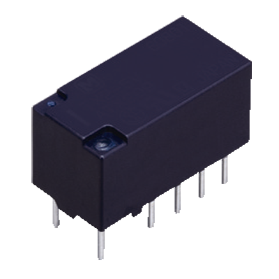
 DS Relays
High sensitivity 200 mW Rated operating power, 1 Form C, 2 A relays
DS Relays
High sensitivity 200 mW Rated operating power, 1 Form C, 2 A relays
-
 GN Relays
High sensitivity, 100 mW operating power, 2 Form C, 1 A, compact size and slim relays
GN Relays
High sensitivity, 100 mW operating power, 2 Form C, 1 A, compact size and slim relays
-
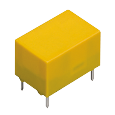
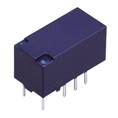
 GQ Relays
High sensitivity, 100 mW operating power, 2 Form C, 2 A, compact size and flat relays
GQ Relays
High sensitivity, 100 mW operating power, 2 Form C, 2 A, compact size and flat relays
-
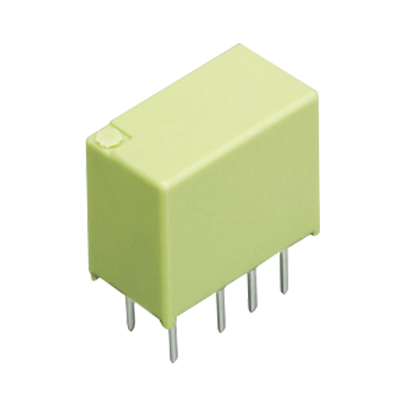
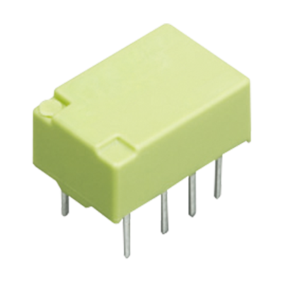
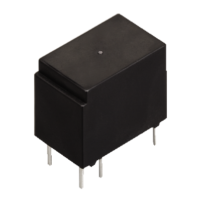
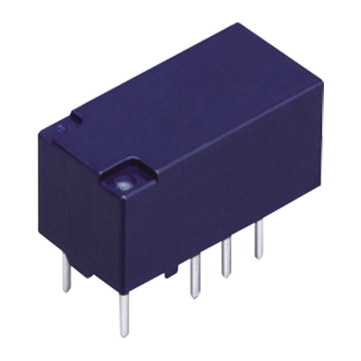
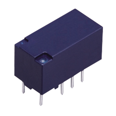
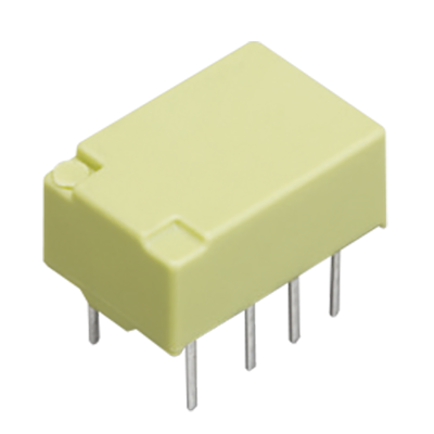 GQ Relays TH Types
Small size controlled 3.5 A inrush current possible
GQ Relays TH Types
Small size controlled 3.5 A inrush current possible
-
 HY Relays
Non-polarized compact 1Form C relay that achieves 150 mW power consumption
HY Relays
Non-polarized compact 1Form C relay that achieves 150 mW power consumption
-
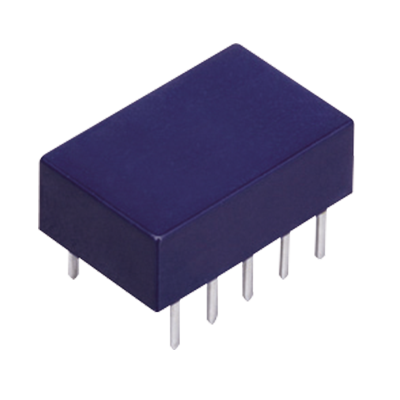 TQ Relays
Flat, 5 mm 2 Form C, 2 A, Surface mount terminal relays
TQ Relays
Flat, 5 mm 2 Form C, 2 A, Surface mount terminal relays
-
 TX Relays
2,000 Vrms dielectric strength, 2 Form C and 2A relays
TX Relays
2,000 Vrms dielectric strength, 2 Form C and 2A relays
-
 TX Relays TH Types
7.5 A inrush current possible, 2 Form C small size relays
TX Relays TH Types
7.5 A inrush current possible, 2 Form C small size relays
-
 TX-D Relays
6,000 V surge withstand voltage, 2 Form C and 2 A high dielectric strength relays
TX-D Relays
6,000 V surge withstand voltage, 2 Form C and 2 A high dielectric strength relays
-
 TX-S Relays
High sensitivity, 50 mW operating power, 2 Form C and 1 A relays
TX-S Relays
High sensitivity, 50 mW operating power, 2 Form C and 1 A relays
-
- CAD data Catalogs/Datasheets
- FAQ
|
Coil data
- Operating characteristics such as ‘Operate voltage’ and ‘Release voltage’ are influenced by mounting conditions, ambient temperature, etc.
Therefore, please use the relay within ± 5% of rated coil voltage. - ‘Initial’ means the condition of products at the time of delivery.
1.Single side stable
| Rated coil voltage | Operate voltage (at 20°C) |
Release voltage (at 20°C) |
Rated operating current (±10%, at 20°C) |
Coil resistance (±10%, at 20°C) |
Rated operating power | Max. applied voltage (at 20°C) |
|---|---|---|---|---|---|---|
| 1.5 V DC | Max. 75% V of rated coil voltage* (Initial) | Min. 10% V of rated coil voltage* (Initial) | 93.8 mA | 16 Ω | 140 mW | 150% V of rated coil voltage |
| 2.4 V DC | 58.5 mA | 41 Ω | ||||
| 3 V DC | 46.7 mA | 64.2 Ω | ||||
| 4.5 V DC | 31 mA | 145 Ω | ||||
| 6 V DC | 23.3 mA | 257 Ω | ||||
| 9 V DC | 15.5 mA | 579 Ω | ||||
| 12 V DC | 11.7 mA | 1,028 Ω | ||||
| 24 V DC | 9.6 mA | 2,504 Ω | 230 mW | 120% V of rated coil voltage |
2.1 coil latching
| Rated coil voltage | Set voltage (at 20°C) |
Reset voltage (at 20°C) |
Rated operating current (±10%, at 20°C) |
Coil resistance (±10%, at 20°C) |
Rated operating power | Max. applied voltage (at 20°C) |
|---|---|---|---|---|---|---|
| 1.5 V DC | Max. 75% V of rated coil voltage* (Initial) | Max. 75% V of rated coil voltage* (Initial) | 66.7 mA | 22.5 Ω | 100 mW | 150% V of rated coil voltage |
| 2.4 V DC | 41.7 mA | 57.6 Ω | ||||
| 3 V DC | 33.3 mA | 90 Ω | ||||
| 4.5 V DC | 22.2 mA | 202.5 Ω | ||||
| 6 V DC | 16.7 mA | 360 Ω | ||||
| 9 V DC | 11.1 mA | 810 Ω | ||||
| 12 V DC | 8.3 mA | 1,440 Ω | ||||
| 24 V DC | 5.0 mA | 4,800 Ω | 120 mW |
| * | Pulse drive (JIS C 5442-1996) |
|---|
Specifications
| Item | Specifications | |
|---|---|---|
| Contact data | Contact arrangement | 2 Form C |
| Contact resistance (Initial) | Max. 100 mΩ (by voltage drop 6 V DC 1 A) | |
| Contact material | AgNi + Au plating | |
| Contact rating (resistive) | 2 A 30 V DC, 1 A 30 V DC, 0.3 A 125 V AC | |
| Max. switching power (resistive) | 60 W (DC), 30 W (DC), 37.5 V A (AC) | |
| Max. switching voltage | 110 V DC, 125 V AC | |
| Max. switching current | 2 A (AC, DC) | |
| Min. switching load (Reference value) *1 | 10 μA 10 mV DC | |
| Rated operating power | Single side stable | 140 mW (1.5 to 12 V DC), 230 mW (24 V DC) |
| 1 coil latching | 100 mW (1.5 to 12 V DC), 120 mW (24 V DC) | |
| Insulation resistance (Initial) | Min. 1,000 MΩ (at 500 V DC) Measured portion is the same as the case of dielectric voltage |
|
| Dielectric strength (initial) |
Between open contacts |
750 Vrms for 1 min (detection current: 10 mA) |
| Between contact and coil |
1,500 Vrms for 1 min (detection current: 10 mA) | |
| Between contact sets |
1,000 Vrms for 1 min (detection current: 10 mA) | |
| Surge withstand voltage (Initial) | Between open contacts |
1,500 V (10 x 160 μs) (FCC Part 68) |
| Between contact and coil |
2,500 V (2 x 10 μs) (Telcordia) | |
| Temperature rise (at 20°C) | Max. 50°C (By resistive method, rated coil voltage applied to the coil; contact carrying current: 2 A) |
|
| Time characteristics (initial) |
Operate time (Set time) (at 20°C) |
Max. 4 ms (Max. 4 ms) (Rated coil voltage applied to the coil, excluding contact bounce time.) |
| Release time (Reset time) (at 20°C) |
Max. 4 ms (Max. 4 ms) (Rated coil voltage applied to the coil, excluding contact bounce time.) (without diode) |
|
| Shock resistance | Functional | 750 m/s2 (half-sine shock pulse: 6 ms; detection time: 10 μs) |
| Destructive | 1,000 m/s2 (half-sine shock pulse: 6 ms.) | |
| Vibration resistance | Functional | 10 to 55 Hz at double amplitude of 3.3 mm (detection time: 10 μs) |
| Destructive | 10 to 55 Hz at double amplitude of 5.0 mm | |
| Expected life | Mechanical | Min. 50 x 106 ope. (at 180 cpm) |
| Electrical | Min. 100 x 103 ope. (1 A 30 V DC resistive) Min. 100 x 103 ope. (3.5 A inrush (250 ms) / 1 A 30 V AC (cosφ = 0.4)) (ON/OFF = 1 s/9 s) |
|
| Conditions | Conditions for operation, transport and storage*2 |
Ambient temperature: (Single side stable, 1 coil latching type) –40 to +85°C Humidity: 5 to 85% RH (Avoid icing and condensation) |
| Unit weight | Approx. 1.0 g | |
| *1 | This value can change due to the switching frequency, environmental conditions, and desired reliability level, therefore it is recommended to check this with the actual load. |
|---|---|
| *2 | Refer to "6.Usage, storage, and transport conditions" in Relays Cautions For Use - 6. Ambient Environment. |
|
Related Information
BY EMAIL


Requests to customers (Automation Control Components & Industrial Device) [Excluding specific product]
Requests to customers (Automation Control Components & Industrial Device) [For specific product]
Requests to customers (FA Sensors & Components [Excluding motors])
Requests to customers (Dedicated to industrial motors)
- COMPONENTS & DEVICES
- FA SENSORS & COMPONENTS
- Fiber Sensors
- Photoelectric Sensors / Laser Sensors
- Micro Photoelectric Sensors
- Light Curtains / Safety Components
- Area Sensors
- Inductive Proximity Sensors
- Particular Use Sensors
- Sensor Options
- Wire-Saving Systems
- Programmable Controllers / Interface Terminal
- Human Machine Interface
- Pressure Sensors / Flow Sensors
- Measurement Sensors
- Static Control Devices
- Laser Markers / 2D Code Readers
- Machine Vision System
- Energy Management Solutions
- Timers / Counters / FA Components
- MOTORS
![]()