[System Maintenance Notice]
Due to ongoing system maintenance, the site search and specification search functions are temporarily unavailable. We apologize for any inconvenience this may cause and appreciate your understanding.

 Business
> Industrial Devices
> Automation Controls Top
> Components & Devices
> Relays / Couplers
> Signal Relays (2A or less)
> Signal Relays (2A or less) Lineup
> TX Relays
> Rating/Performance
Business
> Industrial Devices
> Automation Controls Top
> Components & Devices
> Relays / Couplers
> Signal Relays (2A or less)
> Signal Relays (2A or less) Lineup
> TX Relays
> Rating/Performance
TX Relays
-
Lineup
-
 DS Relays
High sensitivity 200 mW Rated operating power, 1 Form C, 2 A relays
DS Relays
High sensitivity 200 mW Rated operating power, 1 Form C, 2 A relays
-
 GN Relays
High sensitivity, 100 mW operating power, 2 Form C, 1 A, compact size and slim relays
GN Relays
High sensitivity, 100 mW operating power, 2 Form C, 1 A, compact size and slim relays
-
 GQ Relays
High sensitivity, 100 mW operating power, 2 Form C, 2 A, compact size and flat relays
GQ Relays
High sensitivity, 100 mW operating power, 2 Form C, 2 A, compact size and flat relays
-
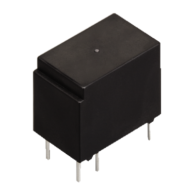
 GQ Relays TH Types
Small size controlled 3.5 A inrush current possible
GQ Relays TH Types
Small size controlled 3.5 A inrush current possible
-
 HY Relays
Non-polarized compact 1Form C relay that achieves 150 mW power consumption
HY Relays
Non-polarized compact 1Form C relay that achieves 150 mW power consumption
-
 TQ Relays
Flat, 5 mm 2 Form C, 2 A, Surface mount terminal relays
TQ Relays
Flat, 5 mm 2 Form C, 2 A, Surface mount terminal relays
-
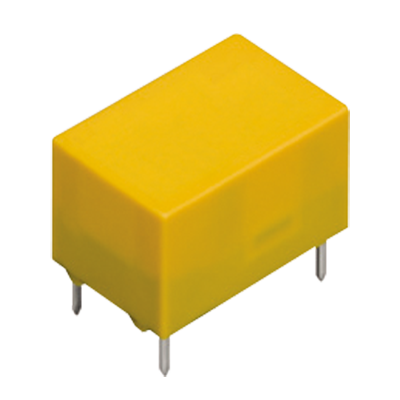
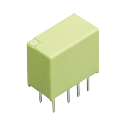
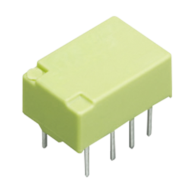
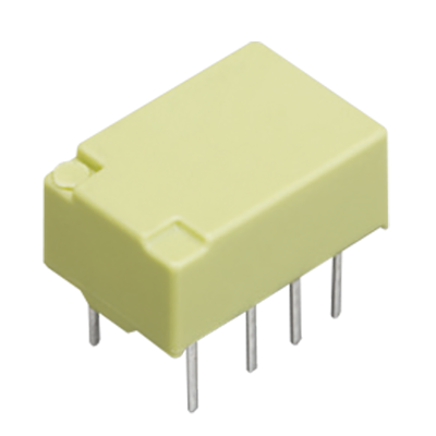
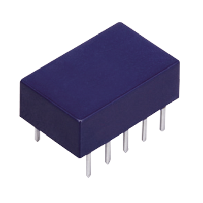
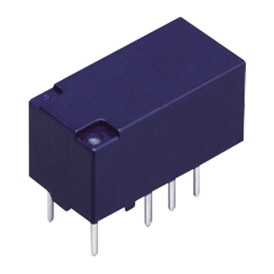
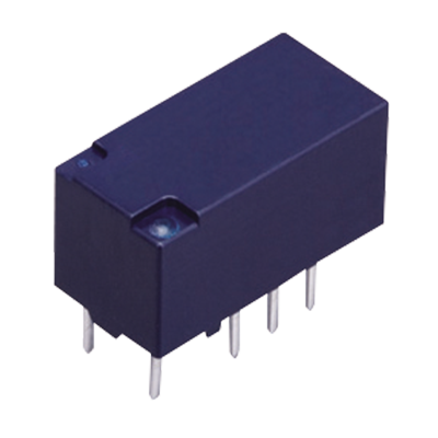
 TX Relays
2,000 Vrms dielectric strength, 2 Form C and 2A relays
TX Relays
2,000 Vrms dielectric strength, 2 Form C and 2A relays
-
 TX Relays TH Types
7.5 A inrush current possible, 2 Form C small size relays
TX Relays TH Types
7.5 A inrush current possible, 2 Form C small size relays
-
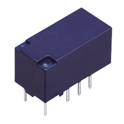
 TX-D Relays
6,000 V surge withstand voltage, 2 Form C and 2 A high dielectric strength relays
TX-D Relays
6,000 V surge withstand voltage, 2 Form C and 2 A high dielectric strength relays
-
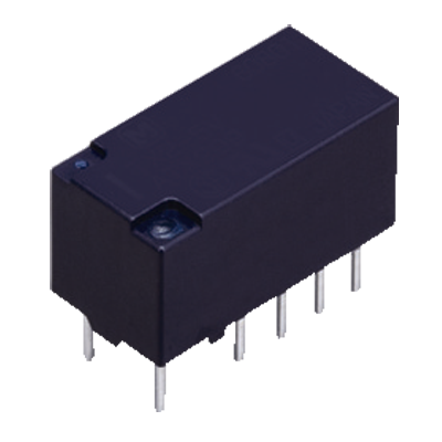
 TX-S Relays
High sensitivity, 50 mW operating power, 2 Form C and 1 A relays
TX-S Relays
High sensitivity, 50 mW operating power, 2 Form C and 1 A relays
-
- CAD data Catalogs/Datasheets
- FAQ
|
Coil data
- Operating characteristics such as "Operate voltage" and "Release voltage" are influenced by mounting conditions, ambient temperature, etc.
Therefore, please use the relay within ± 5% of rated coil voltage. - "Initial" means the condition of products at the time of delivery.
Single side stable type
| Rated coil voltage | Operate voltage* (at 20°C) |
Release voltage* (at 20°C) |
Rated operating current (±10%, at 20°C) |
Coil resistance (±10%, at 20°C) |
Rated operating power | Max. allowable voltage (at 20°C) |
|---|---|---|---|---|---|---|
| 1.5 V DC | Max. 75% V of rated coil voltage (Initial) |
Min. 10% V of rated coil voltage (Initial) |
93.8 mA | 16 Ω | 140 mW | 150% V of rated coil voltage |
| 3 V DC | 46.7 mA | 64.3 Ω | ||||
| 4.5 V DC | 31 mA | 145 Ω | ||||
| 5 V DC | 28.1 mA | 178 Ω | ||||
| 6 V DC | 23.3 mA | 257 Ω | ||||
| 9 V DC | 15.5 mA | 579 Ω | ||||
| 12 V DC | 11.7 mA | 1,028 Ω | ||||
| 24 V DC | 5.8 mA | 4,114 Ω | ||||
| 48 V DC | 5.6 mA | 8,533 Ω | 270 mW | 120% V of rated coil voltage |
| * | square, pulse drive |
|---|
2 coil latching
| Rated coil voltage | Set voltage* (at 20°C) |
Reset voltage* (at 20°C) |
Rated operating current (±10%, at 20°C) |
Coil resistance (±10%, at 20°C) |
Rated operating power | Max. allowable voltage (at 20°C) |
|||
|---|---|---|---|---|---|---|---|---|---|
| Set coil |
Reset coil |
Set coil |
Reset coil |
Set coil |
Reset coil |
||||
| 1.5 V DC | Max. 75% V of rated coil voltage (Initial) |
Max. 75% V of rated coil voltage (Initial) |
133.9 mA | 133.9 mA | 11.2 Ω | 11.2 Ω | 200 mW | 200 mW | 150% V of rated coil voltage |
| 3 V DC | 66.7 mA | 66.7 mA | 45 Ω | 45 Ω | |||||
| 4.5 V DC | 44.5 mA | 44.5 mA | 101.2 Ω | 101.2 Ω | |||||
| 5 V DC | 40 mA |
40 mA |
125 Ω | 125 Ω | |||||
| 6 V DC | 33.3 mA | 33.3 mA | 180 Ω | 180 Ω | |||||
| 9 V DC | 22.2 mA | 22.2 mA | 405 Ω | 405 Ω | |||||
| 12 V DC | 16.7 mA | 16.7 mA | 720 Ω | 720 Ω | |||||
| 24 V DC | 8.3 mA |
8.3 mA |
2,880 Ω | 2,880 Ω | |||||
| * | square, pulse drive |
|---|
Specifications
| Item | Specifications | |||
|---|---|---|---|---|
| Standard contact | AgPd contact (low level load) |
|||
| Contact data | Contact arrangement | 2 Form C | ||
| Contact resistance (initial) |
Max. 100 mΩ (by voltage drop 6 V DC 1 A) | |||
| Contact material | Ag+Au clad | AgPd+Au clad (stationary), AgPd (movable) |
||
| Contact rating (resistive) |
2 A 30 V DC | 1 A 30 V DC | ||
| Max. switching power (resistive) |
60 W (DC) | 30 W (DC) | ||
| Max. switching voltage | 220 V DC | |||
| Max. switching current | 2 A (DC) | 1 A (DC) | ||
| Min. switching load (reference value)*1 |
10 μA 10 mV DC | |||
| Insulation resistance (initial) |
Min. 1,000 MΩ (at 500 V DC, Measured portion is the same as the case of dielectric strength.) | |||
| Dielectric strength (initial) |
Between open contacts |
1,000 Vrms for 1 min (detection current: 10 mA) | ||
| Between contact and coil | 2,000 Vrms for 1 min (detection current: 10 mA) | |||
| Between contact sets | 1,000 Vrms for 1 min (detection current: 10 mA) | |||
| Surge withstand voltage (initial) |
Between open contacts | 1,500 V 10 x 160 μs | ||
| Between contact and coil | 2,500 V 2 x 10 μs | |||
| Time characteristics (initial) |
Operate (Set) time | Max. 4 ms at rated coil voltage (at 20°C, without bounce) [Max. 4ms (at 20°C, without bounce)] |
||
| Release (Reset) time | Max. 4 ms at rated coil voltage (at 20°C, without bounce, without diode) [Max. 4ms (at 20°C, without bounce)] |
|||
| Shock resistance | Functional | 750 m/s2 (half-sine shock pulse: 6 ms, detection time: 10 μs) | ||
| Destructive | 1,000 m/s2 (half-sine shock pulse: 6 ms) | |||
| Vibration resistance | Functional | 10 to 55 Hz (at double amplitude of: 3.3 mm, detection time: 10 μs) | ||
| Destructive | 10 to 55 Hz (at double amplitude of: 5 mm) | |||
| Expected life | Mechanical life | Min. 100 x 106 ope. (Switching frequency: at 180 times/min) | ||
| Conditions | Conditions for usage, transport and storage*2 |
Ambient temperature: -40 to +85°C (1.5 to 24 V DC), -40 to +70°C (48 V DC), (Allowable temperature is from -40 to +70°C at our standard packing condition.) Humidity: 5 to 85% RH (Avoid icing and condensation) |
||
| Unit weight | Approx. 2 g | |||
Note: For AC load, please inquire our sales representative for details.
| *1 | This value is a rough indication of the lower limit at which switching is possible at micro load level. This value can change due to the switching frequency, environmental conditions, and desired reliability level, therefore it is recommended to check this with the actual load. AgPd contact is recommended for low level load (Max. 10 V DC, 10 mA level). |
|---|---|
| *2 | For ambient temperature, please refer to the “GUIDELINES FOR RELAY USAGE”. |
Electrical life
Conditions: resistive load, switching frequency at 20 times / minute
| Type | Switching capacity | Number of operations |
|---|---|---|
| 2 Form C | 1 A 30 V DC | Min. 500 x 103 ope. |
| 2 A 30 V DC | Min. 100 x 103 ope. |
|
Related Information
BY EMAIL


Requests to customers (Automation Control Components & Industrial Device) [Excluding specific product]
Requests to customers (Automation Control Components & Industrial Device) [For specific product]
Requests to customers (FA Sensors & Components [Excluding motors])
Requests to customers (Dedicated to industrial motors)
- COMPONENTS & DEVICES
- FA SENSORS & COMPONENTS
- Fiber Sensors
- Photoelectric Sensors / Laser Sensors
- Micro Photoelectric Sensors
- Light Curtains / Safety Components
- Area Sensors
- Inductive Proximity Sensors
- Particular Use Sensors
- Sensor Options
- Wire-Saving Systems
- Programmable Controllers / Interface Terminal
- Human Machine Interface
- Pressure Sensors / Flow Sensors
- Measurement Sensors
- Static Control Devices
- Laser Markers / 2D Code Readers
- Machine Vision System
- Energy Management Solutions
- Timers / Counters / FA Components
- MOTORS
![]()