[System Maintenance Notice]
Due to ongoing system maintenance, the site search and specification search functions are temporarily unavailable. We apologize for any inconvenience this may cause and appreciate your understanding.

 Business
> Industrial Devices
> Automation Controls Top
> FA Sensors & Components
> Programmable Controllers / Interface Terminal
> Programmable Controllers / Interface Terminal
> FP0R
> Part Number
> AFP0RC32T
Business
> Industrial Devices
> Automation Controls Top
> FA Sensors & Components
> Programmable Controllers / Interface Terminal
> Programmable Controllers / Interface Terminal
> FP0R
> Part Number
> AFP0RC32T
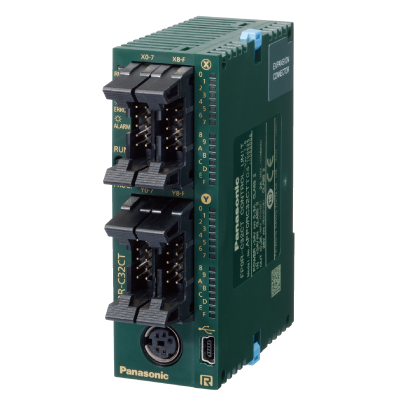
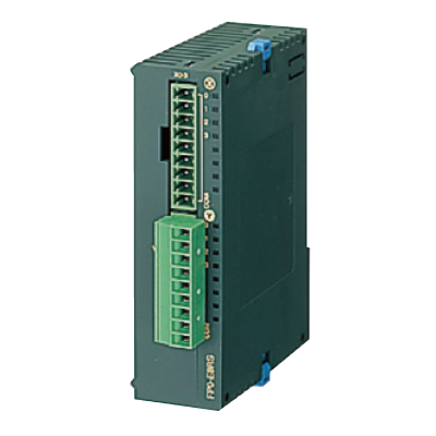
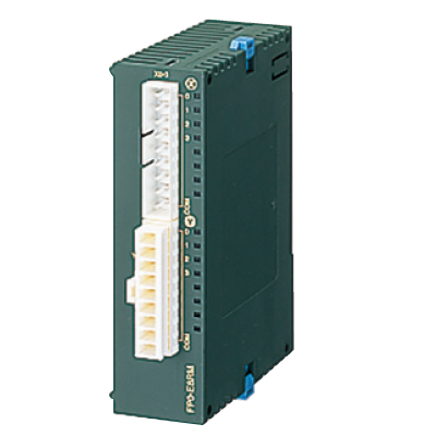
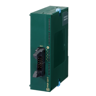
AFP0RC32T | FP0R


|
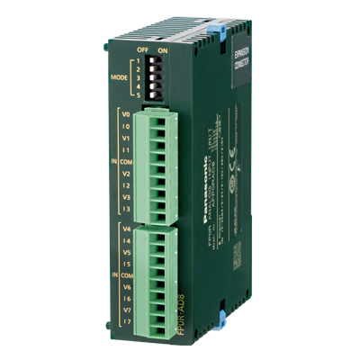
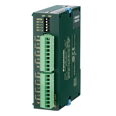
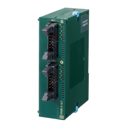
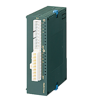
*Photo may vary from actual product.

 This product has been confirmed that it does not contain the 6 substances specified in EU RoHS Directive 2011/65/EU and the 4 substances specified in 2015/863/EU.
| Product Number | AFP0RC32T |
| Part Number | AFP0RC32T |
| Product | FP0R Control unit |
| Details | C32 |
| Product name | FP0R |
As of July 26, 2024
Specifications and design of the products are subject to change without notice for the product improvement.
Spec Detail
| Item | Specifications |
|---|---|
| Product Number | AFP0RC32T |
| Part Number | AFP0RC32T |
Performance specifications
| Item | Specifications |
|---|---|
| Programming method / Control method | Relay symbol / Cyclic operation |
| Number of I/O points : No expansion (Control unit only) | 32 points [Input : 16, Transistor output : 16] |
| Number of I/O points : With expansion 1 Same type of control and expansion units |
Max. 128 points (Note: For the limitations while operating units, reter to the manual.) |
| Number of I/O points : With expansion 2 Mix type of relay and transistor units |
Max. 128 points (Note: For the limitations while operating units, reter to the manual.) |
| Program memory | EEPROM (no backup battery required) |
| Program capacity | 32 k steps |
| Number of instructions : Basic | 110 approx. |
| Number of instructions : High-level | 210 approx. |
| Operation speed : Up to 3,000 steps | Basic instructions : 0.08 μs min. Timer instructions : 2.2 μs min. High-level instructions : 0.32 μs (MV instruction) min. |
| Operation speed : 3,001st and later steps | Basic instructions : 0.58 μs min. Timer instructions : 3.66 μs min. High-level instructions : 1.62 μs (MV instruction) min. |
| Operation memory : Relay : Internal relay (R) | 4,096 points |
| Operation memory : Relay : Timer / Counter (T / C) | 1,024 points |
| Operation memory : Memory area : Data register (DT) | 32,765 words |
| Operation memory : Memory area : Index register (IX, IY) | 14 words (IO to ID) |
| Master control relay points (MCR) | 256 words |
| Number of labels (JMP and LOOP) | 256 labels |
| Differential points | Equivalent to the program capacity |
| Number of step ladder | 1,000 stages |
| Number of subroutines | 500 subroutines |
| Special functions : High speed counter(HSC) | Single-phase 6 points (50 kHz max. each) or 2-phase 3 points (15 kHz max. each) (Note) : For the limitations while operating units, see the manual. |
| Special functions : Pulse output | 4 points (50 kHz max. each) 2 channels can be controlled individually. (Note: For the limitations while operating units, reter to the manual.) |
| Special functions : PWM output | 4 points (6 Hz to 4.8 kHz) |
| Special functions : Pulse catch input / interrupt input | Total 8 points (with high speed counter) |
| Special functions : Interrupt program | Input: 8 programs (6 programs for C10 only) / Periodic: 1 program / High speed counter match, Pulse output match: 4 programs |
| Special functions : Periodical interrupt | In units of 0.5 ms : 0.5 ms to 1.5 sec. / In units of 10 ms : 10 ms to 30 sec. |
| Special functions : Constant scan | In units of 0.5 ms : 0.5 ms to 600 ms |
| Maintenance : Memory backup : Program and system register | Stored program and system register in EEPROM |
| Maintenance : Memory backup : Operation memory | Stored fixed area in EEPROM Counter : 16 points Internal relay : 128 points Data register : 315 words |
| Maintenance : Self-diagnostic function | Watchdog timer (690 ms approx.), Program syntax check |
| Maintenance : Real-time clock function | Not available |
| Maintenance : Other functions | Rewriting in RUN mode (Simultaneous rewriting capacity: 512 steps), Download in RUN mode (All programs), Password function (4-digit, 8-digit), Read protection setting |
General specifications
| Item | Specifications |
|---|---|
| Rated voltage | 24 V DC |
| Operating voltage range | 20.4 to 28.8 V DC |
| Allowed momentary power off time | 10 ms (20.4 V DC or higher) |
| Operating temperature | 0 to +55 ℃ 32 to +131 ℉ |
| Storage temperature | -40 to +70 ℃ -40 to +158 ℉ (-20 ℃ to +70 ℃ -4 to +158 ℉ for T32 only) |
| Operating humidity | 10 to 95% RH (at 25 ℃ 77 ℉, no condensation) |
| Storage humidity | 10 to 95% RH (at 25 ℃ 77 ℉, no condensation) |
| Breakdown voltage (Detection current: 5 mA) | Input terminals - output terminals, Output terminals - power and functional ground terminals --- Transistor output : 500 V AC for 1 minute (Relay output : 1,500 V AC for 1 minute) / Input terminals - power and functional ground terminals, Functional ground terminal - power terminal --- Transistor output : 500 V AC for 1 minute (Relay output : 500 V AC for 1 minute) / Output terminals - output terminals (different common terminals) --- Relay output : 1,500 V AC for 1 minute |
| Insulation resistance (Test voltage: 500 V DC) | Input terminals - output terminals, input terminals - power and functional ground terminals, output terminals - power and functional ground terminals, functional ground terminal - power terminal --- Transistor output : 100 MΩ minimum (relay output : 100 MΩ minimum) / Output terminals - output terminals (different common terminals) --- Relay output : 100 MΩ minimum |
| Vibration resistance | 5 to 9 Hz, single amplitude of 3.5 mm, 1 sweep/min; 9 to 150 Hz, constant acceleration of 9.8 m/s2, 1 sweep/min; for 10 min each in X, Y, and Z directions |
| Shock resistance | 147 m/s2 or more , 4 times each in X, Y, and Z directions |
| Noise resistance | 1,000 V (p-p) with pulse widths 50 ns and 1 μs (using a noise simulator)(Power supply terminal) |
| Operating condition | Free from corrosive gasses and excessive dust |
Input specifications
| Item | Specifications |
|---|---|
| Rated input voltage | 24 V DC |
| Applied voltage range | 21.6 to 26.4 V DC |
| Rated input current | 2.6 mA approx. (at 24 V DC) |
| Input impedance | 9.1 kΩ approx. |
| Input points per common | 16 points / common |
| Min. ON voltage/Min. ON current | 19.2 V / 2 mA |
| Max. OFF voltage/Max. OFF current | 2.4 V / 1.2 mA |
| Response time : OFF→ON | 20 μs or less * An input time constant (0.1 to 64 ms) can be set. |
| Response time : ON→OFF | Same as above |
| Insulation method | Photocoupler |
| Remark | Since the response time of X0 to X7 is very fast (for high-speed counter input) the FP0 happens to chattering noise as an input signal. To prevent this, it is recommended that the timer should be put in the ladder program. |
Output specifications
| Item | Specifications |
|---|---|
| Output type | Open collector |
| Rated load voltage | 5 to 24 V DC |
| Load voltage allowable range | 4.75 to 26.4 V DC |
| Max. load current | 0.2 A / point (Max. 14 per common terminal) |
| OFF state leakage current | 1 μA or less |
| ON state voltage drop | 0.2 V DC or less |
| Response time : OFF→ON | 20 μs or less (Load current : 5 mA or more), 0.1 ms or less (Load current : 0.5 mA or more) |
| Response time : ON→OFF | 40 μs or less (Load current : 5 mA or more), 0.2 ms or less (Load current : 0.5 mA or more) |
| External power : Voltage | 21.6 to 26.4 V DC |
| External power supply : Current | 60 mA or less |
| Surge absorber | Zener diode |
| Output points per common | 16 points / common |
| Insulation method | Photocoupler |
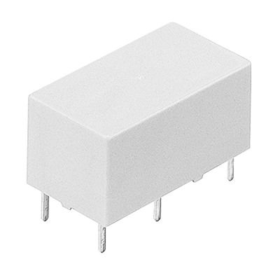
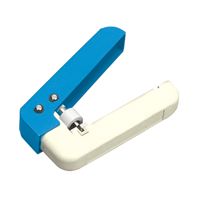
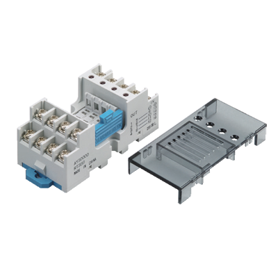
Accessories (Option)


BY EMAIL


Requests to customers (Automation Control Components & Industrial Device) [Excluding specific product]
Requests to customers (Automation Control Components & Industrial Device) [For specific product]
Requests to customers (FA Sensors & Components [Excluding motors])
Requests to customers (Dedicated to industrial motors)
- COMPONENTS & DEVICES
- FA SENSORS & COMPONENTS
- Fiber Sensors
- Photoelectric Sensors / Laser Sensors
- Micro Photoelectric Sensors
- Light Curtains / Safety Components
- Area Sensors
- Inductive Proximity Sensors
- Particular Use Sensors
- Sensor Options
- Wire-Saving Systems
- Programmable Controllers / Interface Terminal
- Human Machine Interface
- Pressure Sensors / Flow Sensors
- Measurement Sensors
- Static Control Devices
- Laser Markers / 2D Code Readers
- Machine Vision System
- Energy Management Solutions
- Timers / Counters / FA Components
- MOTORS
![]()