[System Maintenance Notice]
Due to ongoing system maintenance, the site search and specification search functions are temporarily unavailable. We apologize for any inconvenience this may cause and appreciate your understanding.
【Notification of Manufacturer Change for Panasonic Industrial Devices SUNX Products and Panasonic Industrial Devices SUNX Tatsuno Products】
From April 1, 2024, the terms "Panasonic Industrial Devices SUNX Co., Ltd." and "Panasonic Industrial Devices SUNX Tatsuno Co., Ltd."
in this page and in the manuals and other documents to be downloaded will all be replaced with "Panasonic Industry Co., Ltd." and applied accordingly.
Digital Laser Sensor LS-400
Cautions For Use
| ・ |
This website is a guide to select a suitable product.
Be sure to read the instruction manual attached to the product prior to its use. |
- Never use this product as a sensing device for personnel protection.
- In case of using sensing devices for personnel protection, use products which meet laws and standards, such as OSHA, ANSI or IEC etc., for personnel protection applicable in each region or country.
- Do not operate products using methods other than the ones described in the instruction manual included with each product. Control or adjustment through procedures other than the ones specified may cause hazardous laser radiation exposure.
Cautions for laser beams
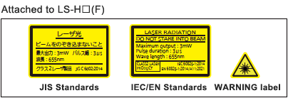
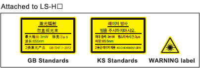
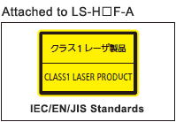
- This product is a class 2 (LS-H□(F)-A is class 1 ) laser product according to IEC/EN/JIS/GB/KS standards and FDA regulations*.
- Avoid observing beams continuously, particularly in a dark surrounding environment.
- Do not look at beams using an optical device such as an optical telephoto system.
- The following label is affixed to this product. Handle the product according to the instruction given on the label.
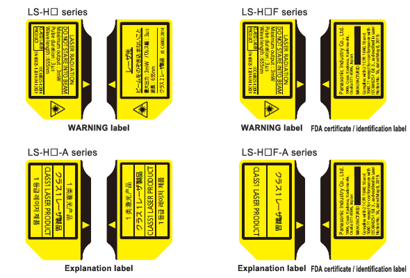
In addition, each product comes with a label according to the standards it complies with.
If necessary, please use it by pasting it on or near the product.
Note) Do not place any other labels over the FDA certification/identification label.
* This product complies with the FDA regulations (FDA 21 CFR 1040.10 and 1040.11) in accordance with FDA Laser Notice No. 56, except for complying with IEC 60825-1 Ed. 3.
Safety standards for laser beam products
- For the purpose of preventing any injury which may occur to the user by the use of the laser product in advance, the following standards have been established by the IEC Standards, EN Standards, JIS Standards, GB Standards, KS Standards and FDA Regulations.
| |
IEC |
: IEC 60825-1:2014 |
| |
EN |
: EN 60825-1:2014/A11:2021 |
| |
JIS |
: JIS C 6802:2014 |
| |
GB |
: GB 7247.1-2012 |
| |
KS |
: KS C IEC 60825-1:2014 |
| |
FDA |
: PART 1040.10, 1040.11(Laser Notice No.56 applied) |
| These standards classifies laser products according to the level of hazard and
provide the safety measures for respective classes.Based on the above standards, LS-H□(F) series is classified as a Class 2 laser product. LS-H□(F)-A series is classified as a Class 1 laser product. |
| Classification |
Description |
| Class 1 |
Lasers that are safe under reasonably foreseeable conditions of operation, including the use of optical instruments for intrabeam viewing. |
| Class 2 |
Lasers that emit visible radiation in the wavelength range from 400 nm to 700 nm where eye protection is normally afforded by aversion responses, including the blink reflex.
This reaction may be expected to provide adequate protection under reasonably foreseeable conditions of operation including the use of optical instruments for intrabeam viewing. |
Note: When an unexpected failure occurs, dangerous radiation may be generated. Therefore, pay special attention to safety.
Safe use of laser products
- For the purpose of preventing users from suffering injuries by laser products, each standard stipulates (Safety of laser products). Kindly check the standards before use.
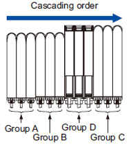
Cautions when connecting amplifiers in cascade
- Refer to connecting conditions written below when connecting amplifiers in cascade.
- When amplifiers are installed, refer to “Cautions on communication function” and use communication function.
|
|
| Group A |
LS-401(P)(-C2), FX-301(P):Previous version unit (Note 1),FX-301G(P)/B(P)/H(P), FX-41□(P) |
| Group B |
FX-301(P): Updated version unit (Note 1),FX-301(P)-C1, FX-305(P) (Note 2) |
| Group C |
LS-403, DPS-400 series,SC-T1JA |
| Group D |
FX-500 series |
|
Notes:
| 1) |
The previous version unit is manufactured before June 2004.
The updated version unit is manufactured after June 2004. |
| 2) |
Be sure to install FX-305 behind FX-301. |
Cautions on communication function
Copy function / channel bank
function (when communicating) |
Conditions when using SC-GU2-C |
Interference prevention function |
Each group should be cascaded in a lump.
When group A, group B and group C are connected together in cascade, as for the products that are located between different groups, put the amplifier protection seal (FX-MB1 optional) on the amplifier communication window of each corresponding product. Interference prevention function cannot be used if amplifier protection seal is put on the amplifier communication window. Choose one from copy function / channel bank function (communication) or interference prevention function to be used. |
[Group A]
It cannot communicate with master.
[Group B, Group C]
They can communicate with master.
When group B and group C are connected together in cascade, be sure that group B is located on the left side of group C. |
Each group should be cascaded in a lump.
When group A, group B and group C are connected together in cascade, refer to the connecting conditions for connecting. (Copy function cannot be used.) |
When not using group A, copy function / channel bank function (communication) and interference prevention function can be used without putting on the amplifier protection seal.
(Follow the connecting conditions when connecting.) |
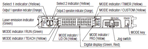
Part description (Amplifier)
Spot-shape adjuster (Only for LS-H21□, LS-H22□)
- The diffuse reflective type LS-H21□ and LS-H22□ incorporate the spot-shape adjuster to adjust the shape of spots.
| Spot-shape adjuster |
Description |
 |
Turn the spot-shape adjuster clockwise or counter-clockwise to adjust the spot shape at your desired detecting distance. However, if the adjuster is turned too far, it may be damaged. |
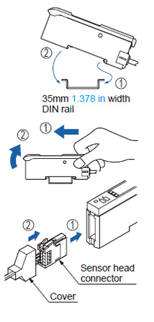
Mounting
<How to mount the amplifier>
| ① |
Fit the rear part of the mounting section of the amplifier on a 35 mm 1.378 in width DIN rail. |
| ② |
Press down the rear part of the mounting section of the unit on the 35 mm 1.378 in width DIN rail and fit the front part of the mounting section to the DIN rail. |
<How to remove the amplifier>
| ① |
Push the amplifier forward. |
| ② |
Lift up the front part of the amplifier to remove it. |
Note:
|
Be careful. If the front part is lifted without pushing the amplifier forward, the hook on the rear portion of the mounting section is likely to break. |
<How to mount the sensor head>
| ① |
Insert the sensor head connector into the inlet until it clicks. |
| ② |
Fit the cover to the connector. |
|
|
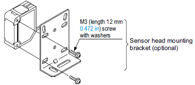
- The tightening torque should be 0.5 N·m or less.
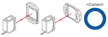
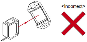
- When placing the sensor head horizontally or vertically, the reflector must also be positioned horizontally or vertically as shown in Fig. 1 below.
If the sensor head is placed horizontally or vertically but the reflector is leaned as shown in Fig. 2 below, the reflection amount will decrease, which may cause unstable detection.
| Fig. 1 Proper positioning |
When placing the sensor head horizontally or vertically, the reflector shall also be positioned horizontally or vertically.
| Fig. 2 Improper positioning |
When placing the sensor head horizontally or vertically, but the reflector is leaned. |
|
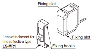
Lens attachment for line reflective type (LS-MR1)
- The lens attachment for line reflective type LS-MR1 mounted in the long sensing range line reflective type LS-H22□ is removable.
When LS-H22□ is used without LS-MR1, it will provide the equivalent performance to the long sensing range spot reflective type LS-H21□. In addition, the optional LS-MR1 can be attached to LS-H21□ to obtain the performance equivalent to LS-H22□.
- Keep the lens clean of dust, dirt, water, oil, grease, etc.
- Do not apply any excessive force to LS-MR1.
Such force may cause damage.
| ① |
Insert a screwdriver into the fixing slot located at the top of sensor head. |
| ② |
Tilt the screwdriver inserted in Step ① to remove LS-MR1. |
| ① |
The size of upper fixing hook of LS-MR1 is not same as the lower fixing hook. After identifying the upper and lower fixing hooks, insert LS-MR1 upper fixing hook into the fixing slot at the top of sensor head and then insert LS-MR1 lower fixing hook into the fixing slot at the bottom of sensor head. |
| ② |
After mounting, check that LS-MR1 is properly fixed to the sensor head. |
|
|
Wiring
- Make sure that the power supply is off while wiring.
- Verify that the supply voltage variation is within the rating.
- Take care that if a voltage exceeding the rated range is applied, or if an AC power supply is directly connected, the sensor may get burnt or damaged.
- Take care that short-circuit or wrong wiring of the load may burn or damage the sensor.
- Do not run the wires together with high-voltage lines or power lines or put them in the same raceway. This can cause malfunction due to induction.
- Ensure that an isolation transformer is utilized for the DC power supply. If an auto transformer is utilized, the main amplifier or power supply may be damaged.
- Make sure to use the optional quick-connection cable for the connection of the amplifier [connector type LS-401(P) / LS-403]. Extension up to total 100 m 328.084 ft is possible with 0.3 mm2, or more,cable. However, in order to reduce noise, make the wiring as short as possible.
Others
- Do not use during the initial transient time (0.5 sec. approx.) after the power supply is switched on.
- Because the sensitivity is higher in U-LG mode than in other modes, it can be more easily affected by extraneous noise.
Check the operating environment before use.
- These sensors are only for indoor use.
- Avoid dust, dirt, and steam.
- Take care that the product does not come in direct contact with water, oil, grease, or organic solvents, such as, thinner, etc.
- This sensor cannot be used in an environment containing inflammable or explosive gasses.
- Never disassemble or modify the sensor.
Return to top
Return to top

 Business
> Industrial Devices
> Automation Controls Top
> FA Sensors & Components
> Sensors
> Photoelectric Sensors / Laser Sensors
> Digital Laser Sensor LS-400
> Cautions For Use
Business
> Industrial Devices
> Automation Controls Top
> FA Sensors & Components
> Sensors
> Photoelectric Sensors / Laser Sensors
> Digital Laser Sensor LS-400
> Cautions For Use