[System Maintenance Notice]
Due to ongoing system maintenance, the site search and specification search functions are temporarily unavailable. We apologize for any inconvenience this may cause and appreciate your understanding.
【Notification of Manufacturer Change for Panasonic Industrial Devices SUNX Products and Panasonic Industrial Devices SUNX Tatsuno Products】
From April 1, 2024, the terms "Panasonic Industrial Devices SUNX Co., Ltd." and "Panasonic Industrial Devices SUNX Tatsuno Co., Ltd."
in this page and in the manuals and other documents to be downloaded will all be replaced with "Panasonic Industry Co., Ltd." and applied accordingly.

 Business
> Industrial Devices
> Automation Controls Top
> FA Sensors & Components
> Sensors
> Photoelectric Sensors / Laser Sensors
> Robust Photoelectric Sensor RX(Discontinued Products)
> Specifications
Business
> Industrial Devices
> Automation Controls Top
> FA Sensors & Components
> Sensors
> Photoelectric Sensors / Laser Sensors
> Robust Photoelectric Sensor RX(Discontinued Products)
> Specifications
Robust Photoelectric Sensor RX (Discontinued Products)
|
We are sorry, the products have been discontinued. Please refer to the details of the discontinued products and the recommended substitutes list below.
|
|
Specifications
Standard type
| Type | Thru-beam | ||
|---|---|---|---|
| Infrared | |||
| Long sensing range |
|||
| Model No. | RX-M10 | RX-M50 | |
| CE marking directive compliance | EMC Directive, RoHS Directive | ||
| Sensing range | 10 m 32.808 ft |
50 m 164.042 ft |
|
| Sensing object | φ10 mm 0.394 in or more opaque object (Note 4) | ||
| Hysteresis | - | ||
| Repeatability (perpendicular to sensing axis) |
0.5 mm 0.020 in or less | ||
| Supply voltage | 12 to 24 V DC ±10 % Ripple P-P 10 % or less | ||
| Current consumption | Emitter: 20 mA or less (RX-M50: 25 mA or less), Receiver: 25 mA or less |
||
| Sensing output | NPN open-collector transistor • Maximum sink current: 100 mA • Applied voltage: 30 V DC or less (between sensing output and 0 V) • Residual voltage: 2 V or less (at 100 mA sink current), 1 V or less (at 16 mA sink current) |
||
| Utilization category | DC-12 or DC-13 | ||
| Output operation | Switchable either Light-ON or Dark-ON | ||
| Short-circuit protection |
Incorporated | ||
| Self-diagnosis output | NPN open-collector transistor • Maximum sink current: 50 mA • Applied voltage: 30 V DC or less (between self-diagnosis output and 0 V) • Residual voltage: 1.5 V or less (at 50 mA sink current), 1 V or less (at 16 mA sink current) |
||
| Output operation | ON under unstable sensing condition | ||
| Short-circuit protection |
- | ||
| Response time | 1 ms or less | ||
| Test input (emission halt) function |
Incorporated | ||
| Operation indicator | Red LED (lights up when the sensing output is ON) | ||
| Stability indicator | Green LED (lights up under stable light received condition or stable dark condition) |
||
| Emitting indicator | Red LED (lights up during beam emission) | ||
| Sensitivity adjuster | Continuously variable adjuster | ||
| Automatic interference prevention function |
- | ||
| Pollution degree | 3 (Industrial environmrnt) | ||
| Protection | IP67 (IEC) | ||
| Ambient temperature | –25 to +60 ℃ –13 to +140 ℉ (No dew condensation or icing allowed), Storage: –30 to +70 ℃ –22 to +158 ℉ |
||
| Ambient humidity | 35 to 85 % RH, Storage: 35 to 85 % RH | ||
| Ambient illuminance | Incandescent light: 3,500 Lx or less at the light-receiving face | ||
| Voltage withstandability |
1,000 V AC for one min. between all supply terminals connected together and enclosure | ||
| Insulation resistance | 20 MΩ, or more, with 250 V DC megger between all supply terminals connected together and enclosure | ||
| Vibration resistance | 10 to 500 Hz frequency, 1.5 mm 0.059 in double amplitude (10 G max.) in X, Y and Z directions for two hours each | ||
| Shock resistance | 500 m/s2 acceleration (50 G approx.) in X, Y and Z directions three times each | ||
| Emitting element (modulated) |
Infrared LED | ||
| Peak emission wavelength |
880 nm 0.035 mil |
||
| Material | Enclosure: Die-cast zinc alloy, Indicator cover: Polyethersulphone, Lens: Polycarbonate |
||
| Cable | Emitter: 0.15 mm2 3-core oil, heat and cold resistant cabtyre cable, 2 m 6.562 ft long Receiver: 0.15 mm2 4-core oil, heat and cold resistant cabtyre cable, 2 m 6.562 ft long |
||
| Cable extension | Extension up to total 100 m 328.084 ft is possible with 0.3 mm2, or more, cable (thru-beam type: both emitter and receiver). |
||
| Net weight | Emitter: 70 g approx. (RX-M50: 75 g approx.) Receiver: 70 g approx. (RX-M50: 75 g approx.) |
||
| Accessories | MS-RX-1 (Sensor mounting bracket) : 1 set for emitter and receiver Adjusting screwdriver : 1 pc. |
||
| Type | Retroreflective | Diffuse reflective | |
|---|---|---|---|
| Infrared (Long sensing range) |
Infrared | ||
| Model No. | RX-RVM5 | RX-D700 | |
| CE marking directive compliance | EMC Directive, RoHS Directive | ||
| Sensing range | 0.1 to 5 m 0.328 to 16.404 ft (Note 2) |
700 mm 27.559 in (Note 3) |
|
| Sensing object | φ50 mm φ1.969 in or more opaque, or translucent object (Note 2, 5) |
Opaque, translucent or transparent object (Note 5) |
|
| Hysteresis | - | 15 % or less of operation distance (Note 3) |
|
| Repeatability (perpendicular to sensing axis) |
1 mm 0.039 in or less | 0.5 mm 0.020 in or less | |
| Supply voltage | 12 to 24 V DC ±10 % Ripple P-P 10 % or less | ||
| Current consumption | 40 mA or less | ||
| Sensing output | NPN open-collector transistor • Maximum sink current: 100 mA • Applied voltage: 30 V DC or less (between sensing output and 0 V) • Residual voltage: 2 V or less (at 100 mA sink current), 1 V or less (at 16 mA sink current) |
||
| Utilization category | DC-12 or DC-13 | ||
| Output operation | Switchable either Light-ON or Dark-ON | ||
| Short-circuit protection |
Incorporated | ||
| Self-diagnosis output | NPN open-collector transistor • Maximum sink current: 50 mA • Applied voltage: 30 V DC or less (between self-diagnosis output and 0 V) • Residual voltage: 1.5 V or less (at 50 mA sink current), 1 V or less (at 16 mA sink current) |
||
| Output operation | ON under unstable sensing condition | ||
| Short-circuit protection |
- | ||
| Response time | 1 ms or less | ||
| Test input (emission halt) function |
Incorporated | ||
| Operation indicator | Red LED (lights up when the sensing output is ON) | ||
| Stability indicator | Green LED (lights up under stable light received condition or stable dark condition) |
||
| Emitting indicator | - | ||
| Sensitivity adjuster | Continuously variable adjuster | ||
| Automatic interference prevention function |
Incorporated (Two units of sensors can be mounted close together.) | ||
| Pollution degree | 3 (Industrial environmrnt) | ||
| Protection | IP67 (IEC) | ||
| Ambient temperature | –25 to +60 ℃ –13 to +140 ℉ (No dew condensation or icing allowed), Storage: –30 to +70 ℃ –22 to +158 ℉ |
||
| Ambient humidity | 35 to 85 % RH, Storage: 35 to 85 % RH | ||
| Ambient illuminance | Incandescent light: 3,500 Lx or less at the light-receiving face | ||
| Voltage withstandability |
1,000 V AC for one min. between all supply terminals connected together and enclosure | ||
| Insulation resistance | 20 MΩ, or more, with 250 V DC megger between all supply terminals connected together and enclosure | ||
| Vibration resistance | 10 to 500 Hz frequency, 1.5 mm 0.059 in double amplitude (10 G max.) in X, Y and Z directions for two hours each | ||
| Shock resistance | 500 m/s2 acceleration (50 G approx.) in X, Y and Z directions three times each | ||
| Emitting element (modulated) |
Infrared LED | ||
| Peak emission wavelength |
880 nm 0.035 mil |
||
| Material | Enclosure: Die-cast zinc alloy, Indicator cover: Polyethersulphone, Lens: Polycarbonate (Retroreflective type: Acrylic) |
||
| Cable | 0.15 mm2 5-core oil, heat and cold resistant cabtyre cable, 2 m 6.562 ft long |
||
| Cable extension | Extension up to total 100 m 328.084 ft is possible with 0.3 mm2, or more, cable | ||
| Net weight | 75 g approx. | ||
| Accessories | MS-RX-1 (Sensor mounting bracket): 1 set RF-230 (Reflector): 1 pc. Adjusting screwdriver: 1 pc. |
MS-RX-1 (Sensor mounting bracket): 1 set Adjusting screwdriver: 1 pc. |
|
Notes:
| 1) | Where measurement conditions have not been specified precisely, the conditions used were an ambient temperature of +23 ℃ +73.4 ℉. |
|---|---|
| 2) | The sensing range and the sensing object for the retroreflective type sensor are specified for the RF-230 reflector. Further, the sensing range of RX-PRVM3 and RX-RVM5 is the possible setting range for the reflector. The sensor can detect an object less than 0.1 m 0.328 ft away. |
| 3) | The sensing range and the hysteresis of the diffuse reflective type sensor are specified for white non-glossy paper (200 x 200 mm 7.874 x 7.874 in) as the object. |
| 4) | If slit masks (optional) are fitted on RX-M10, an object of 0.5 x 5 mm 0.020 x 0.197 in can be detected. |
| 5) | Make sure to confirm detection with an actual sensor before use. |
| Type | Thru-beam | ||
|---|---|---|---|
| Red | Green | ||
| Model No. | RX-M2R | RX-500G | |
| CE marking directive compliance | EMC Directive, RoHS Directive | ||
| Sensing range | 2 m 6.562 ft |
500 mm 19.685 in |
|
| Sensing object | φ10 mm 0.394 in or more opaque object (Note 4) | ||
| Hysteresis | - | ||
| Repeatability (perpendicular to sensing axis) |
0.5 mm 0.020 in or less | ||
| Supply voltage | 12 to 24 V DC ±10 % Ripple P-P 10 % or less | ||
| Current consumption | Emitter: 20 mA or less (RX-M50: 25 mA or less), Receiver: 25 mA or less |
||
| Sensing output | NPN open-collector transistor • Maximum sink current: 100 mA • Applied voltage: 30 V DC or less (between sensing output and 0 V) • Residual voltage: 2 V or less (at 100 mA sink current), 1 V or less (at 16 mA sink current) |
||
| Utilization category | DC-12 or DC-13 | ||
| Output operation | Switchable either Light-ON or Dark-ON | ||
| Short-circuit protection |
Incorporated | ||
| Self-diagnosis output | NPN open-collector transistor • Maximum sink current: 50 mA • Applied voltage: 30 V DC or less (between self-diagnosis output and 0 V) • Residual voltage: 1.5 V or less (at 50 mA sink current), 1 V or less (at 16 mA sink current) |
||
| Output operation | ON under unstable sensing condition | ||
| Short-circuit protection |
- | ||
| Response time | 1 ms or less | ||
| Test input (emission halt) function |
Incorporated | ||
| Operation indicator | Red LED (lights up when the sensing output is ON) | ||
| Stability indicator | Green LED (lights up under stable light received condition or stable dark condition) |
||
| Emitting indicator | Red LED (lights up during beam emission) | ||
| Sensitivity adjuster | Continuously variable adjuster | ||
| Automatic interference prevention function |
- | ||
| Pollution degree | 3 (Industrial environmrnt) | ||
| Protection | IP67 (IEC) | ||
| Ambient temperature | –25 to +60 ℃ –13 to +140 ℉ (No dew condensation or icing allowed), Storage: –30 to +70 ℃ –22 to +158 ℉ |
||
| Ambient humidity | 35 to 85 % RH, Storage: 35 to 85 % RH | ||
| Ambient illuminance | Incandescent light: 3,500 Lx or less at the light-receiving face | ||
| Voltage withstandability |
1,000 V AC for one min. between all supply terminals connected together and enclosure | ||
| Insulation resistance | 20 MΩ, or more, with 250 V DC megger between all supply terminals connected together and enclosure | ||
| Vibration resistance | 10 to 500 Hz frequency, 1.5 mm 0.059 in double amplitude (10 G max.) in X, Y and Z directions for two hours each | ||
| Shock resistance | 500 m/s2 acceleration (50 G approx.) in X, Y and Z directions three times each | ||
| Emitting element (modulated) |
Red LED | Green LED | |
| Peak emission wavelength |
660 nm 0.026 mil |
570 nm 0.022 mil |
|
| Material | Enclosure: Die-cast zinc alloy, Indicator cover: Polyethersulphone, Lens: Polycarbonate |
||
| Cable | Emitter: 0.15 mm2 3-core oil, heat and cold resistant cabtyre cable, 2 m 6.562 ft long Receiver: 0.15 mm2 4-core oil, heat and cold resistant cabtyre cable, 2 m 6.562 ft long |
||
| Cable extension | Extension up to total 100 m 328.084 ft is possible with 0.3 mm2, or more, cable (thru-beam type: both emitter and receiver). |
||
| Net weight | Emitter: 70 g approx. (RX-M50: 75 g approx.) Receiver: 70 g approx. (RX-M50: 75 g approx.) |
||
| Accessories | MS-RX-1 (Sensor mounting bracket) : 1 set for emitter and receiver Adjusting screwdriver : 1 pc. |
||
| Type | Retroreflective | Diffuse reflective | |
|---|---|---|---|
| Red (with polarizing filters) |
GreReden | ||
| Model No. | RX-PRVM3 | RX-D200R | |
| CE marking directive compliance | EMC Directive, RoHS Directive | ||
| Sensing range | 0.1 to 3 m 0.328 to 9.843 ft (Note 2) |
200 mm 7.874 in (Note 3) |
|
| Sensing object | φ50 mm φ1.969 in or more opaque, translucent or specular object (Note 2, 4) |
Opaque, translucent or transparent object (Note 4) |
|
| Hysteresis | - | 15 % or less of operation distance (Note 3) |
|
| Repeatability (perpendicular to sensing axis) |
1 mm 0.039 in or less | 0.5 mm 0.020 in or less | |
| Supply voltage | 12 to 24 V DC ±10 % Ripple P-P 10 % or less | ||
| Current consumption | 40 mA or less | ||
| Sensing output | NPN open-collector transistor • Maximum sink current: 100 mA • Applied voltage: 30 V DC or less (between sensing output and 0 V) • Residual voltage: 2 V or less (at 100 mA sink current), 1 V or less (at 16 mA sink current) |
||
| Utilization category | DC-12 or DC-13 | ||
| Output operation | Switchable either Light-ON or Dark-ON | ||
| Short-circuit protection |
Incorporated | ||
| Self-diagnosis output | NPN open-collector transistor • Maximum sink current: 50 mA • Applied voltage: 30 V DC or less (between self-diagnosis output and 0 V) • Residual voltage: 1.5 V or less (at 50 mA sink current), 1 V or less (at 16 mA sink current) |
||
| Output operation | ON under unstable sensing condition | ||
| Short-circuit protection |
- | ||
| Response time | 1 ms or less | ||
| Test input (emission halt) function |
Incorporated | ||
| Operation indicator | Red LED (lights up when the sensing output is ON) | ||
| Stability indicator | Green LED (lights up under stable light received condition or stable dark condition) |
||
| Emitting indicator | - | ||
| Sensitivity adjuster | Continuously variable adjuster | ||
| Automatic interference prevention function |
Incorporated (Two units of sensors can be mounted close together.) | ||
| Pollution degree | 3 (Industrial environmrnt) | ||
| Protection | IP67 (IEC) | ||
| Ambient temperature | –25 to +60 ℃ –13 to +140 ℉ (No dew condensation or icing allowed), Storage: –30 to +70 ℃ –22 to +158 ℉ |
||
| Ambient humidity | 35 to 85 % RH, Storage: 35 to 85 % RH | ||
| Ambient illuminance | Incandescent light: 3,500 Lx or less at the light-receiving face | ||
| Voltage withstandability |
1,000 V AC for one min. between all supply terminals connected together and enclosure | ||
| Insulation resistance | 20 MΩ, or more, with 250 V DC megger between all supply terminals connected together and enclosure | ||
| Vibration resistance | 10 to 500 Hz frequency, 1.5 mm 0.059 in double amplitude (10 G max.) in X, Y and Z directions for two hours each | ||
| Shock resistance | 500 m/s2 acceleration (50 G approx.) in X, Y and Z directions three times each | ||
| Emitting element (modulated) |
Red LED | Red LED | |
| Peak emission wavelength |
680 nm 0.027 mil |
680 nm 0.027 mil |
|
| Material | Enclosure: Die-cast zinc alloy, Indicator cover: Polyethersulphone, Lens: Polycarbonate (Retroreflective type: Acrylic) |
||
| Cable | 0.15 mm2 5-core oil, heat and cold resistant cabtyre cable, 2 m 6.562 ft long |
||
| Cable extension | Extension up to total 100 m 328.084 ft is possible with 0.3 mm2, or more, cable | ||
| Net weight | 75 g approx. | ||
| Accessories | MS-RX-1 (Sensor mounting bracket): 1 set RF-230 (Reflector): 1 pc. Adjusting screwdriver: 1 pc. |
MS-RX-1 (Sensor mounting bracket): 1 set Adjusting screwdriver: 1 pc. |
|
Notes:
| 1) | Where measurement conditions have not been specified precisely, the conditions used were an ambient temperature of +23 ℃ +73.4 ℉. |
|---|---|
| 2) | The sensing range and the sensing object for the retroreflective type sensor are specified for the RF-230 reflector. Further, the sensing range of RX-PRVM3 and RX-RVM5 is the possible setting range for the reflector. The sensor can detect an object less than 0.1 m 0.328 ft away.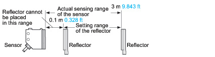 |
| 3) | The sensing range and the hysteresis of the diffuse reflective type sensor are specified for white non-glossy paper (200 x 200 mm 7.874 x 7.874 in) as the object. |
| 4) | Make sure to confirm detection with an actual sensor before use. |
DC 2-wire type
| Type | Thru-beam | Retroreflective (with polarizing filters) |
Diffuse reflective | |
|---|---|---|---|---|
| Model No. | RX2-M5 | RX2-PRVM2 | RX2-D300 | |
| Sensing range | 5 m 16.404 ft |
0.1 to 2 m 0.328 to 6.562 ft (Note 2) |
300 mm 11.811 in (Note 3) |
|
| Sensing object | φ10 mm φ0.394 in or more opaque object (Note 4) |
φ50 mm φ1.969 in or more opaque, translucent or specular object (Note 2, 5) |
Opaque, translucent or transparent object (Note 5) |
|
| Hysteresis | - | - | 15 % or less of operation distance (Note 3) |
|
| Repeatability (perpendicular to sensing axis) |
0.5 mm 0.020 in or less | 1 mm 0.039 in or less | 0.5 mm 0.020 in or less | |
| Supply voltage | 12 to 24 V DC ±10 % Ripple P-P 10 % or less | |||
| Current consumption | Emitter: 8 mA or less, Receiver: 0.8 mA or less (Note 6) |
1 mA or less (Note 6) |
||
| Sensing output | Non contact DC 2-wire type • Load current: 5 to 100 mA • Residual voltage: 4 V or less (Note 7) |
|||
| Output operation | Switchable either Light-ON or Dark-ON | |||
| Short-circuit protection |
Incorporated | |||
| Response time | 3 ms or less | |||
| Operation indicator | Red LED (lights up when the output is ON) | |||
| Stability indicator | Green LED (Light-ON mode: lights up under stable light received condition Dark-ON mode: lights up under stable dark condition) |
|||
| Emitting indicator | Red LED (lights up during beam emission) |
- | ||
| Sensitivity adjuster | Continuously variable adjuster | |||
| Protection | IP67 (IEC) | |||
| Ambient temperature | –20 to +60 ℃ –4 to +140 ℉ (No dew condensation or icing allowed), Storage: –30 to +70 ℃ –22 to +158 ℉ |
|||
| Ambient humidity | 35 to 85 % RH, Storage: 35 to 85 % RH | |||
| Ambient illuminance | Incandescent light: 3,500 Lx or less at the light-receiving face | |||
| Voltage withstandability | 1,000 V AC for one min. between all supply terminals connected together and enclosure | |||
| Insulation resistance | 20 MΩ, or more, with 250 V DC megger between all supply terminals connected together and enclosure | |||
| Vibration resistance | 10 to 500 Hz frequency, 1.5 mm 0.059 in double amplitude (10 G max.) in X, Y and Z directions for two hours each | |||
| Shock resistance | 500 m/s2 acceleration (50 G approx.) in X, Y and Z directions three times each | |||
| Emitting element | Infrared LED (modulated) |
Red LED (modulated) |
Infrared LED (modulated) |
|
| Peak emission wavelength |
880 nm 0.035 mil | 680 nm 0.027 mil | 890 nm 0.035 mil | |
| Material | Enclosure: Die-cast zinc alloy, Indicator cover: Polyethersulphone, Lens: Polycarbonate (RX2-PRVM2: Acrylic) | |||
| Cable | 0.15 mm2 2-core oil, heat and cold resistant cabtyre cable, 2 m 6.562 ft long | |||
| Cable extension | - (Note 7) | |||
| Net weight | Emitter: 70 g approx., Receiver: 70 g approx. |
75 g approx. | 70 g approx. | |
| Accessories | MS-RX-1 (Sensor mounting bracket): 1 set for emitter and receiver Adjusting screwdriver: 1 pc. |
MS-RX-1 (Sensor mounting bracket): 1 set RF-230 (Reflector): 1 pc. Adjusting screwdriver: 1 pc. |
MS-RX-1 (Sensor mounting bracket): 1 set Adjusting screwdriver: 1 pc. |
|
Notes:
| 1) | Where measurement conditions have not been specified precisely, the conditions used were an ambient temperature of +23 ℃ +73.4 ℉. |
|---|---|
| 2) | The sensing range and the sensing object for RX2-PRVM2 are specified for the RF-230 reflector. Further, the sensing range is the possible setting range for the reflector. The sensor can detect an object less than 0.1 m 0.328 ft away. |
| 3) | The sensing range and the hysteresis of RX2-D300 are specified for white non-glossy paper (200 x 200 mm 7.874 x 7.874 in) as the object. |
| 4) | If slit masks (optional) are fitted, an object of 0.5 x 5 mm 0.020 x 0.197 in can be detected. |
| 5) | Make sure to confirm detection with an actual sensor before use. |
| 6) | It is the leakage current when the output is in the OFF state. |
| 7) | When extending the cable, the residual voltage will be increased depending on the type of cable used. Verify the residual voltage when extending the cable. |
Heavy duty type
| Type | Thru-beam | |||
|---|---|---|---|---|
| Cable length 2 m 6.562 ft |
Cable length 3 m 9.843 ft |
Cable length 5 m 16.404 ft |
||
| Model No. | RX4-M5 | RX4-M5-C3 | RX4-M5-C5 | |
| Sensing range | 5 m 16.404 ft | |||
| Sensing object | φ10 mm φ0.394 in or more opaque object | |||
| Repeatability (perpendicular to sensing axis) |
0.5 mm 0.020 in or less | |||
| Supply voltage | 12 to 24 V DC ±10 % Ripple P-P 10 % or less | |||
| Current consumption | Emitter: 20 mA or less, Receiver: 25 mA or less | |||
| Sensing output | NPN open-collector transistor • Maximum sink current: 100 mA • Applied voltage: 30 V DC or less (between sensing output and 0 V) • Residual voltage: 2 V or less (at 100 mA sink current), 1 V or less (at 16 mA sink current) |
|||
| Output operation | Switchable either Light-ON or Dark-ON | |||
| Short-circuit protection |
Incorporated | |||
| Self-diagnosis output | NPN open-collector transistor • Maximum sink current: 50 mA • Applied voltage: 30 V DC or less (between self-diagnosis output and 0 V) • Residual voltage: 1.5 V or less (at 50 mA sink current), 1 V or less (at 16 mA sink current) |
|||
| Output operation | ON under unstable sensing condition | |||
| Short-circuit protection |
- | |||
| Response time | 1 ms or less | |||
| Test input (emission halt) function |
Incorporated | |||
| Operation indicator | Red LED (lights up when the sensing output is ON) | |||
| Stability indicator | Green LED (lights up under stable light received condition or stable dark condition) |
|||
| Emitting indicator | Red LED (lights up during beam emission) | |||
| Sensitivity adjuster | Continuously variable adjuster | |||
| Protection | IP67 (IEC), IP67G | |||
| Ambient temperature | –25 to +60 ℃ –13 to +140 ℉ (No dew condensation or icing allowed), Storage: –30 to +70 ℃ –22 to +158 ℉ |
|||
| Ambient humidity | 35 to 85 % RH, Storage: 35 to 85 % RH | |||
| Ambient illuminance | Incandescent light: 3,500 Lx or less at the light-receiving face | |||
| Voltage withstandability | 1,000 V AC for one min. between all supply terminals connected together and enclosure | |||
| Insulation resistance | 20 MΩ, or more, with 250 V DC megger between all supply terminals connected together and enclosure | |||
| Vibration resistance | 10 to 500 Hz frequency, 1.5 mm 0.059 in double amplitude (10 G max.) in X, Y and Z directions for two hours each | |||
| Shock resistance | 500 m/s2 acceleration (50 G approx.) in X, Y and Z directions three times each | |||
| Emitting element | Infrared LED (Peak emission wavelength: 880 nm 0.035 mil, modulated) | |||
| Material | Enclosure: Die-cast zinc alloy (Fluorine resin coating), Indicator cover: Polyethersulphone, Lens: Polyalylate, Protective tube sheath: Oil resistant PVC |
|||
| Cable | 0.15 mm2 4-core (emitter: 3-core) oil, heat and cold resistant cabtyre cable | |||
| Protective tube length | 1 m 3.281 ft | 2 m 6.562 ft | 4 m 13.123 ft | |
| Cable extension | Extension up to total 100 m 328.084 ft is possible for both emitter and receiver with 0.3 mm2, or more, cable. | |||
| Net weight | Emitter: 175 g approx., Receiver: 175 g approx. |
Emitter: 265 g approx., Receiver: 265 g approx. |
Emitter: 495 g approx., Receiver: 495 g approx. |
|
| Accessories | MS-RX-2 (Sensor mounting bracket): 1 set for emitter and receiver, Adjusting screwdriver: 1 pc. |
|||
Note:
Where measurement conditions have not been specified precisely, the conditions used were an ambient temperature of +23 ℃ +73.4 ℉.
BY EMAIL
- U.S.A.
- +1-800-344-2112
- Europe
- +49-89-45354-1000
- China
- +86-10-59255988
- Singapore
- +65-6299-9181


Requests to customers (Automation Control Components & Industrial Device) [Excluding specific product]
Requests to customers (Automation Control Components & Industrial Device) [For specific product]
Requests to customers (FA Sensors & Components [Excluding motors])
Requests to customers (Dedicated to industrial motors)
- COMPONENTS & DEVICES
- FA SENSORS & COMPONENTS
- Fiber Sensors
- Photoelectric Sensors / Laser Sensors
- Micro Photoelectric Sensors
- Light Curtains / Safety Components
- Area Sensors
- Inductive Proximity Sensors
- Particular Use Sensors
- Sensor Options
- Wire-Saving Systems
- Programmable Controllers / Interface Terminal
- Human Machine Interface
- Pressure Sensors / Flow Sensors
- Measurement Sensors
- Static Control Devices
- Laser Markers / 2D Code Readers
- Machine Vision System
- Energy Management Solutions
- Timers / Counters / FA Components
- MOTORS
![]()