[System Maintenance Notice]
Due to ongoing system maintenance, the site search and specification search functions are temporarily unavailable. We apologize for any inconvenience this may cause and appreciate your understanding.
【Notification of Manufacturer Change for Panasonic Industrial Devices SUNX Products and Panasonic Industrial Devices SUNX Tatsuno Products】
From April 1, 2024, the terms "Panasonic Industrial Devices SUNX Co., Ltd." and "Panasonic Industrial Devices SUNX Tatsuno Co., Ltd."
in this page and in the manuals and other documents to be downloaded will all be replaced with "Panasonic Industry Co., Ltd." and applied accordingly.
Cylindrical Inductive Proximity Sensor GX-U/GX-FU/GX-N (Discontinued Products)
We are sorry, the products have been discontinued. Please refer to the details of the discontinued products and the recommended substitutes list below.
 |
September 30, 2022 |
|
|
Cautions For Use
<All models>
- Never use this product as a sensing device for personnel protection.
- In case of using sensing devices for personnel protection, use products which meet laws and standards, such as OSHA, ANSI or IEC etc., for personnel protection applicable in each region or country.
Mounting
- The tightening torque should be under the value given below.
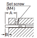
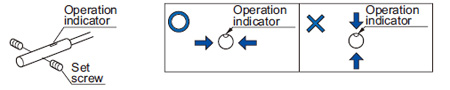
| Mounting with a set screw |
- Tighten with the cup-point of a set screw (M4).
<Non-threaded type> |
|
| Mounting hole process dimension |
|
 |
|
 |
| Model No. |
A (mm in) |
B (mm in) |
C (mm in) |
Tightening torque |
| GX-5SU(B) |
5 to 30 0.197 to 1.181 |
3 0.118 |
ø5.5+ 0.20 ø0.217+ 0.0080 |
0.29 N·m (Note) |
| Note : |
From the shipment on October, 2019. |
- Do not fix on the operation indicator and opposite to it.
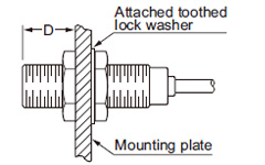
<Shielded of threaded type> |
|---|
 |
|
|
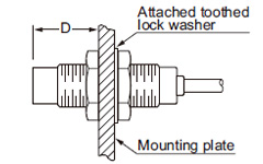
<Non-shielded of threaded type> |
|---|
 |
|
|
| Model No. |
Dimension D (mm in) |
Tightening torque |
| GX-8MU(B) |
3 to 10.3 0.118 to 0.406 |
5.9 N·m |
| 10.3 0.406 or more |
11.8 N·m |
GX-12MU(B)
GX-F12MU-J
GX-N12M(B) |
3.5 to 13.5 0.138 to 0.531 |
10 N·m |
| 13.5 0.531 or more |
20 N·m |
GX-18MU(B)
GX-F18MU-J
GX-N18M(B) |
4 to 18 0.157 to 0.709 |
45 N·m |
| 18 0.709 or more |
80 N·m |
GX-30MU(B)
GX-F30MU-J
GX-N30M(B) |
5 to 21 0.197 to 0.827 |
80 N·m |
| 21 0.827 or more |
180 N·m |
| GX-8MLU(B) |
12 0.472 or more |
11.8 N·m |
GX-12MLU(B)
GX-N12ML(B) |
15 0.591 or more |
20 N·m |
GX-18MLU(B)
GX-N18ML(B) |
25 0.984 or more |
80 N·m |
GX-30MLU(B)
GX-N30ML(B) |
30 1.181 or more |
180 N·m |
| Note: |
Mount such that the nuts do not protrude from the threaded portion. |
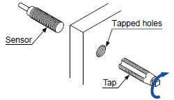
- The root truncation of the threads is shallow owing to strengthening of the sensors against tightening.
When tapping holes on equipment to fix the sensors, the prepared holes must be value in the table below.
 |
|
| Model No. |
Prepared hole |
GX-8MU(B)
GX-8MLU(B) |
ø7.2 mm
ø0.283 in |
GX-12MU(B)
GX-12MLU(B)
GX-F12MU-J
GX-N12M(B)
GX-N12ML(B) |
ø11.2 mm
ø0.441 in |
|
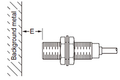
Distance from surrounding metal
- As metal around the sensor may affect the sensing performance, pay attention to the following points.
| Influence of surrounding metal |
- The surrounding metal will affect the sensing performance. Keep the minimum distance specified in the table below.
 |
|
| Model No. |
E (mm in) |
| GX-5SU(B) |
4.5 0.177 |
| GX-8MU(B) |
4.5 0.177 |
GX-12MU(B)
GX-F12MU-J
GX-N12M(B) |
8 0.315 |
GX-18MU(B)
GX-F18MU-J
GX-N18M(B) |
20 0.787 |
GX-30MU(B)
GX-F30MU-J
GX-N30M(B) |
40 1.575 |
| GX-8MLU(B) |
8 0.315 |
GX-12MLU(B)
GX-N12ML(B) |
22 0.866 |
GX-18MLU(B)
GX-N18ML(B) |
45 1.772 |
GX-30MLU(B)
GX-N30ML(B) |
75 2.953 |
|
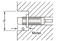
| Embedding of the sensor in metal |
- Sensing range may decrease if the sensor is completely embedded in metal. Especially for the non-threaded type and the non-shielded type, keep the minimum distance specified in the table below.
 |
|
| Model No. |
F (mm in) |
G (mm in) |
| GX-5SU(B) |
ø12 ø0.472 |
3 0.118 |
| GX-8MLU(B) |
ø24 ø0.945 |
12 0.472 |
GX-12MLU(B)
GX-N12ML(B) |
ø50 ø1.969 |
15 0.591 |
GX-18MLU(B)
GX-N18ML(B) |
ø75 ø2.953 |
25 0.984 |
GX-30MLU(B)
GX-N30ML(B) |
ø105 ø4.134 |
30 1.181 |
|
| Note: |
With the non-shielded type, the sensing
range may vary depending on the position
of the nuts. |
|
|
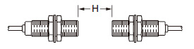
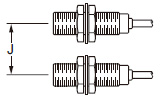
Mutual interference
- When two or more sensors are installed in parallel or face to face, keep the minimum separation distance specified below to avoid mutual interference.
|
|
| Model No. |
H (mm in) |
J (mm in) |
| GX-5SU(B) |
19 0.748 |
14 0.551 |
| GX-8MU(B) |
20 0.787 |
15 0.591 |
GX-12MU(B)
GX-F12MU-J |
35 1.378 |
20 0.787 |
GX-18MU(B)
GX-F18MU-J |
70 2.756 |
45 1.772 |
GX-30MU(B)
GX-F30MU-J |
115 4.528 |
70 2.756 |
| GX-8MLU(B) |
60 2.362 |
45 1.772 |
| GX-12MLU(B) |
145 5.709 |
95 3.740 |
| GX-18MLU(B) |
250 9.843 |
165 6.496 |
| GX-30MLU(B) |
350 13.780 |
250 9.843 |
| GX-N12M(B) |
25 0.984 |
15 0.591 |
| GX-N18M(B) |
50 1.969 |
35 1.378 |
| GX-N30M(B) |
90 3.543 |
55 2.165 |
| GX-N12ML(B) |
120 4.724 |
70 2.756 |
| GX-N18ML(B) |
180 7.087 |
125 4.921 |
| GX-N30ML(B) |
290 1.417 |
190 7.480 |
|
Sensing range
- The sensing range is specified for the standard sensing object. With a non-ferrous metal, the sensing range is obtained by multiplying with the correction coefficient specified below. Further, the sensing range also changes if the sensing object is smaller than the standard sensing object or if the sensing object is plated.
Correction coefficient
| |
Iron |
Stainless steel
(SUS304) |
Brass |
Aluminum |
| GX-5SU(B) |
1 |
0.63 approx. |
0.32 approx. |
0.30 approx. |
| GX-8MU(B) |
1 |
0.59 approx. |
0.32 approx. |
0.29 approx. |
GX-12MU(B)
GX-F12MU-J |
1 |
0.75 approx. |
0.51 approx. |
0.49 approx. |
GX-18MU(B)
GX-F18MU-J |
1 |
0.75 approx. |
0.50 approx. |
0.48 approx. |
GX-30MU(B)
GX-F30MU-J |
1 |
0.69 approx. |
0.44 approx. |
0.42 approx. |
| GX-8MLU(B) |
1 |
0.64 approx. |
0.38 approx. |
0.38 approx. |
| GX-12MLU(B) |
1 |
0.67 approx. |
0.44 approx. |
0.43 approx. |
| GX-18MLU(B) |
1 |
0.68 approx. |
0.45 approx. |
0.43 approx. |
| GX-30MLU(B) |
1 |
0.67 approx. |
0.44 approx. |
0.43 approx. |
| GX-N12M(B) |
1 |
0.77 approx. |
0.52 approx. |
0.51 approx. |
| GX-N18M(B) |
1 |
0.73 approx. |
0.50 approx. |
0.48 approx. |
| GX-N30M(B) |
1 |
0.70 approx. |
0.45 approx. |
0.44 approx. |
| GX-N12ML(B) |
1 |
0.66 approx. |
0.44 approx. |
0.43 approx. |
| GX-N18ML(B) |
1 |
0.68 approx. |
0.46 approx. |
0.44 approx. |
| GX-N30ML(B) |
1 |
0.65 approx. |
0.44 approx. |
0.43 approx. |
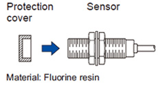
Protection cover (Optional)
- It protects the sensing surface from welding sparks (spatter), etc.
 |
|
| Model No. |
Applicable model No. |
| MS-H12 |
GX-12MU(B)
GX-N12M(B) |
| MS-H18 |
GX-18MU(B)
GX-N18M(B) |
| MS-H30 |
GX-30MU(B)
GX-N30M(B) |
|
| Note: |
Mount the protection cover so that there is no gap between it and the sensing surface. |
Others
- Do not use during the initial transient time (50 ms) after the power supply is switched on.
- Make sure that stress by forcible bend or pulling is not applied directly to the sensor cable joint.
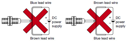
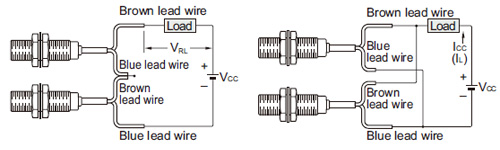
<DC 2-wire type>
Wiring
- The sensor must be connected to a power supply via a load. If the sensor is connected to a power supply without a load, the short-circuit protection makes the sensor inoperable. (The output stays in the OFF state and the indicator does not light up.) In this case, rectify by connecting the power supply via a load. Now, the sensor becomes operable. Further, take care that if the power supply is connected with reverse polarity without a load, the sensor will get damaged.
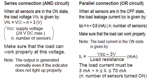
- For series connection (AND circuit) or parallel connection (OR circuit) of sensors, take care of the following.
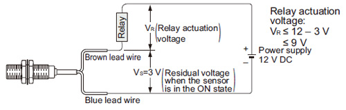
- The residual voltage of the sensor is 3 V. Before connecting a relay as the load, take care of its actuation voltage.
(Some 12 V relays may not be usable.)
2-color indicator [GX-(F)□U(-J) only]
- When the sensing object is in the stable sensing range, the LED lights up in green, and when the sensing object is in the unstable sensing range, the LED lights up in orange. While the LED lights up in green, the sensing is performed stably without being affected by temperature drifts or voltage fluctuations.
Return to top
Return to top

 Business
> Industrial Devices
> Automation Controls Top
> FA Sensors & Components
> Sensors
> Inductive Proximity Sensors
> Cylindrical Inductive Proximity Sensor GX-U/GX-FU/GX-N(Discontinued Products)
> Cautions For Use
Business
> Industrial Devices
> Automation Controls Top
> FA Sensors & Components
> Sensors
> Inductive Proximity Sensors
> Cylindrical Inductive Proximity Sensor GX-U/GX-FU/GX-N(Discontinued Products)
> Cautions For Use
![2-color indicator [GX-(F)□U(-J) only]](/ac/e/fasys/sensor/proximity/gx-u_gx-n/attention/images/pic16.jpg)


