[System Maintenance Notice]
Due to ongoing system maintenance, the site search and specification search functions are temporarily unavailable. We apologize for any inconvenience this may cause and appreciate your understanding.
【Notification of Manufacturer Change for Panasonic Industrial Devices SUNX Products and Panasonic Industrial Devices SUNX Tatsuno Products】
From April 1, 2024, the terms "Panasonic Industrial Devices SUNX Co., Ltd." and "Panasonic Industrial Devices SUNX Tatsuno Co., Ltd."
in this page and in the manuals and other documents to be downloaded will all be replaced with "Panasonic Industry Co., Ltd." and applied accordingly.
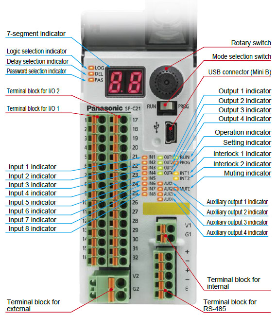
Safety Control Unit SF-C21
I/O Circuit and Wiring diagrams
TERMINAL ARRANGEMENT DIAGRAM
[Terminal block for I/O 1]
Terminal
No. |
Terminal
name |
Function |
| 1 |
IN1 |
Safety input 1 |
| 2 |
T1 |
Safety input 1 / test output |
| 3 |
IN2 |
Safety input 2 |
| 4 |
T2 |
Safety input 2 / test output |
| 5 |
IN3 |
Safety input 3 |
| 6 |
T3 |
Safety input 3 / test output |
| 7 |
IN4 |
Safety input 4 |
| 8 |
T4 |
Safety input 4 / test output |
| 9 |
MUTE1 |
Muting indicator output 1_1 |
| 10 |
NC |
Not connected |
| 11 |
INT11 |
Reset input 1 / test output |
| 12 |
INT12 |
Reset input 1 |
| 13 |
AUX1 |
Auxiliary output 1 |
| 14 |
AUX2 |
Auxiliary output 2 |
| 15 |
AUX3 |
Auxiliary output 3 |
| 16 |
AUX4 |
Auxiliary output 4 |
[Power supply
for external]
Terminal
No. |
Terminal
name |
Function |
| V2 |
V2 |
Power supply for control output /
power supply for auxiliary output (+V) |
| G2 |
G2 |
Power supply for control output /
power supply for auxiliary output (0V) |
|
|
[Terminal block for I/O 2]
Terminal
No. |
Terminal
name |
Function |
| 17 |
IN5 |
Safety input 5 |
| 18 |
T5 |
Safety input 5 / test output |
| 19 |
IN6 |
Safety input 6 |
| 20 |
T6 |
Safety input 6 / test output |
| 21 |
IN7 |
Safety input 7 |
| 22 |
T7 |
Safety input 7 / test output |
| 23 |
IN8 |
Safety input 8 |
| 24 |
T8 |
Safety input 8 / test output |
| 25 |
MUTE2 |
Muting indicator output 1_2 |
| 26 |
NC |
Not connected |
| 27 |
INT21 |
Reset input 2 / test output |
| 28 |
INT22 |
Reset input 2 |
| 29 |
OUT1 |
Control output 1 |
| 30 |
OUT2 |
| 31 |
OUT3 |
Control output 2 |
| 32 |
OUT4 |
[Power supply for internal]
Terminal
No. |
Terminal
name |
Function |
| V1 |
V1 |
Power supply for safety input (+V) |
| G1 |
G1 |
Power supply for safety input (0V) |
[RS-485]
Terminal
No. |
Terminal
name |
Function |
| + |
+ |
Transmission line(+) |
| - |
- |
Transmission line(-) |
| + |
+ |
Transmission line(+) |
| - |
- |
Transmission line(-) |
| E |
E |
Terminal station setting |
|
| Note: |
For an input device requiring a separate power supply, such as a safety light curtain, use the same power supply as the power supply for internal. |
Connection examples
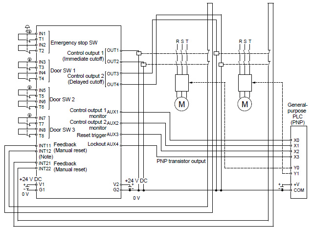
Logic No.1 Overall stop control (Manual reset mode) |
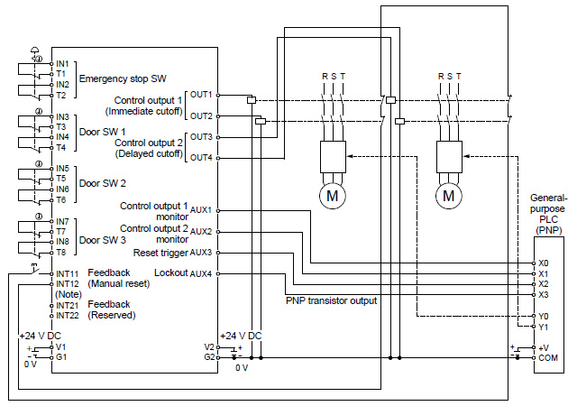 |
| Note: |
Select contacts that can support the micro load of 6 mA at 24 V DC as the reset switch and contacts used for INT11 / INT12 (INT21 / INT22). |
|
|
Logic No.1 Overall stop control (Auto reset mode)
|
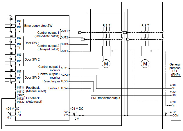 |
| Note: |
Select contacts that can support the micro load of 6 mA at 24 V DC as the reset switch and contacts used for INT11 / INT12 (INT21 / INT22). |
|
|
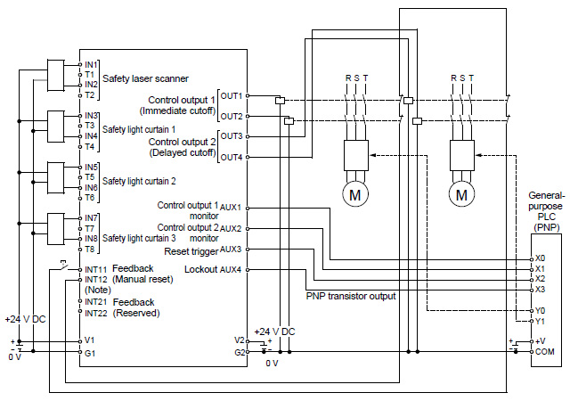
Logic No.4 Partial stop control 1 (Manual reset mode)
|
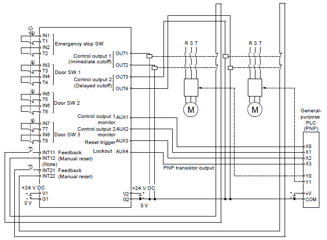 |
| Note: |
Select contacts that can support the micro load of 6 mA at 24 V DC as the reset switch and contacts used for INT11 / INT12 (INT21 / INT22). |
|
|
Customization example, based on logic No.4 Partial stop control 1 (Auto reset mode)
|
 |
| Note: |
Select contacts that can support the micro load of 6 mA at 24 V DC as the reset switch and contacts used for INT11 / INT12 (INT21 / INT22). |
|
|
Customization example, based on logic No.1 Overall stop control (Manual reset, when all input devices are changed to PNP input × 2)
|
 |
| Note: |
Select contacts that can support the micro load of 6 mA at 24 V DC as the reset switch and contacts used for INT11 / INT12 (INT21 / INT22). |
|
|
Customization example, based on logic No.1 Overall stop control (Manual reset, when input 3 to 8 are changed to devices with 1NC / 1NO)
|
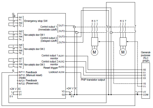 |
| Note: |
Select contacts that can support the micro load of 6 mA at 24 V DC as the reset switch and contacts used for INT11 / INT12 (INT21 / INT22). |
|
|
Return to top
Return to top

 Business
> Industrial Devices
> Automation Controls Top
> FA Sensors & Components
> Sensors
> Light Curtains / Safety Components
> Safety Control Unit SF-C21
> I/O Circuit and Wiring diagrams
Business
> Industrial Devices
> Automation Controls Top
> FA Sensors & Components
> Sensors
> Light Curtains / Safety Components
> Safety Control Unit SF-C21
> I/O Circuit and Wiring diagrams