[System Maintenance Notice]
Due to ongoing system maintenance, the site search and specification search functions are temporarily unavailable. We apologize for any inconvenience this may cause and appreciate your understanding.
【Notification of Manufacturer Change for Panasonic Industrial Devices SUNX Products and Panasonic Industrial Devices SUNX Tatsuno Products】
From April 1, 2024, the terms "Panasonic Industrial Devices SUNX Co., Ltd." and "Panasonic Industrial Devices SUNX Tatsuno Co., Ltd."
in this page and in the manuals and other documents to be downloaded will all be replaced with "Panasonic Industry Co., Ltd." and applied accordingly.
Compact & Robust Safety Light Curtain [Type 4 PLe SIL3] SF4D
I/O Circuit and Wiring diagrams
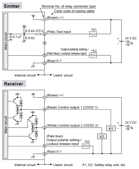
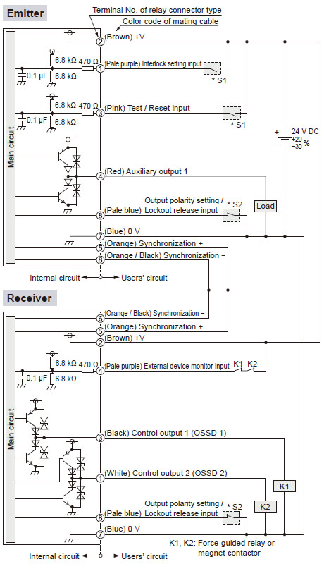
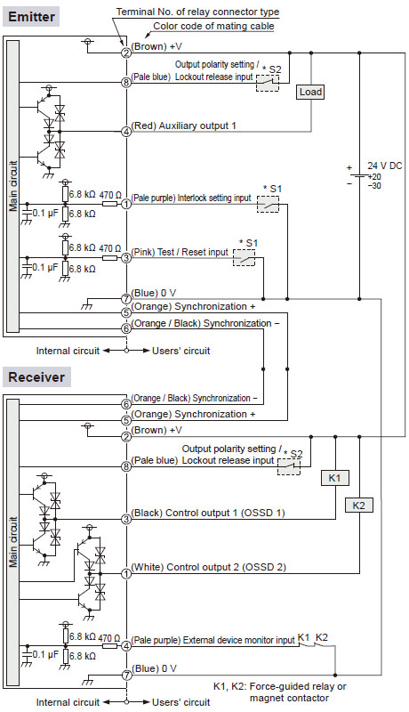
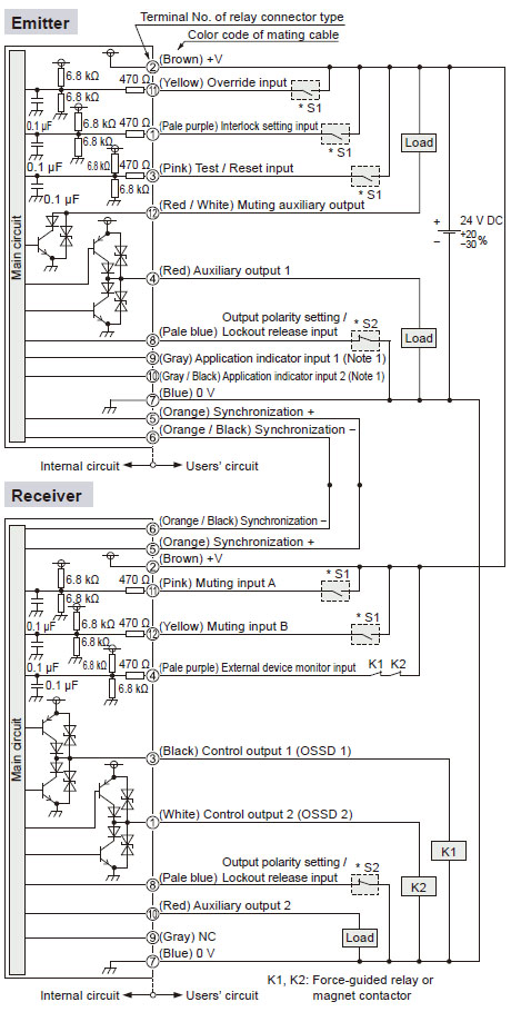
I/O circuit diagram (using optical synchronization setting and 5-core cable, Not connected in series / parallel)
<In case of using I/O circuit for PNP output> |
 |
|
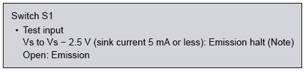
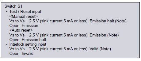
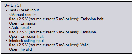
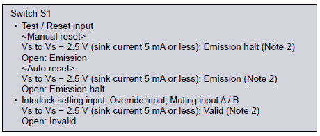
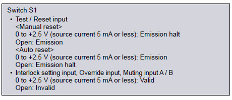
* S1 |
 |
|
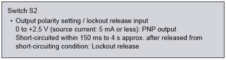
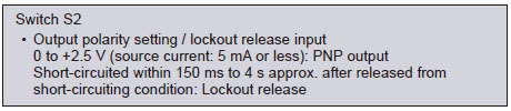
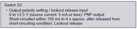
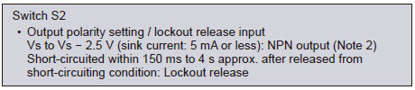
* S2 |
 |
| Note: Vs is the applying supply voltage. |
|
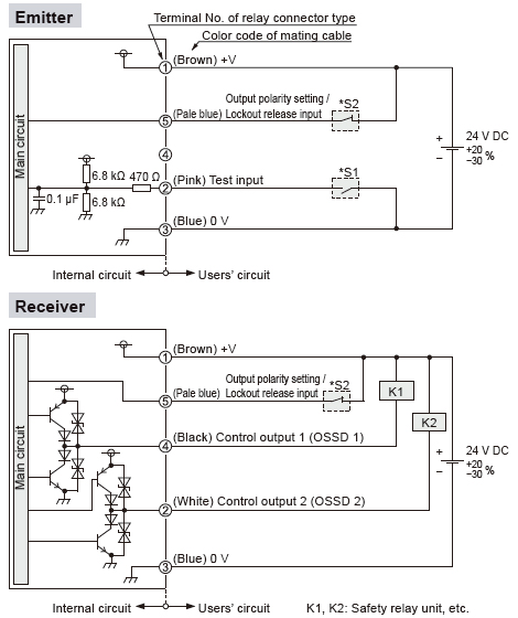
<In case of using I/O circuit for NPN output> |
 |
|
* S1 |
 |
|
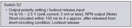
* S2 |
 |
| Note: Vs is the applying supply voltage. |
|
I/O circuit diagram (using line synchronization setting and 8-core cable, not connected in series / parallel)
<In case of using I/O circuit for PNP output> |
 |
|
* S1 |
 |
|
* S2 |
 |
| Note: Vs is the applying supply voltage. |
|
<In case of using I/O circuit for NPN output> |
 |
|
* S1 |
 |
|
* S2 |
 |
| Note: Vs is the applying supply voltage. |
|
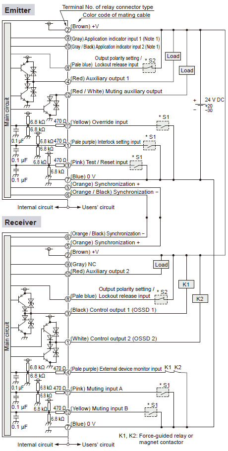
I/O circuit diagram (using line synchronization setting and 12-core cable, not connected in series / parallel)
<In case of using I/O circuit for PNP output> |
 |
|
*S1 |
 |
|
*S2 |
 |
Notes:
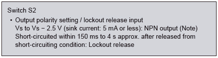
1) Vs to Vs - 2.5 V (sink current: 5 mA or less): ON (Note 2), Open: OFF
2) Vs is the applying supply voltage. |
|
<In case of using I/O circuit for NPN output> |
 |
|
*S1 |
 |
|
*S2 |
 |
Notes:
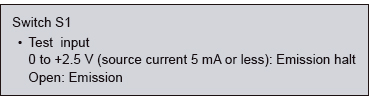
1) 0 to +2.5 V (sink current: 5 mA or less): ON, Open: OFF
2) Vs is the applying supply voltage. |
|
Return to top
Return to top

 Business
> Industrial Devices
> Automation Controls Top
> FA Sensors & Components
> Sensors
> Light Curtains / Safety Components
> Compact & Robust Safety Light Curtain [Type 4 PLe SIL3] SF4D
> I/O Circuit and Wiring diagrams
Business
> Industrial Devices
> Automation Controls Top
> FA Sensors & Components
> Sensors
> Light Curtains / Safety Components
> Compact & Robust Safety Light Curtain [Type 4 PLe SIL3] SF4D
> I/O Circuit and Wiring diagrams


